Considering the fine wire in the moving coil armature and the extremely low currents generated I feel tone arm wiring is very critical. It must have minimum number of interfaces on the way and should be twisted and very well screened.
I decided to use litz wire but in a different way. I have grouped strands in the single litz wire to be the +/- signal pairs. And applied shiled over it.
The leakge inductance measured was about 30-40mH measured from +/- ends from one side and +/- ends shorted on the other side. This value is very high.
This is very strange since litz strands are tightly coupled with each other.
(Tight coupling reduces series inductance and increases EMI imunity.)
I would appreciate any clarifying comments.
How were you conducting the measurement? How many +/- pairs?
I have used a 24 strand litz wire. Grouped in 12 strand pairs.
Strands for grouping selected randomly for + and - signals.
When both ends are open + to minus capacitance is measured 2nF.
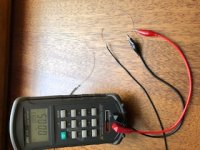
I have measured mutual coupling with one end +/- wires shorted, connecting a digital LCR meter with 120hz and 1khz measurement capability, at the other +/- signal wires.
Just like you measure leakage inductance of a transformer.
My mistake,
I measured inductance in parallel mode.
Series inductance is 500 nano henries for 110cm lenght cable.
Which is much much better then I expected.
I measured inductance in parallel mode.
Series inductance is 500 nano henries for 110cm lenght cable.
Which is much much better then I expected.

Picking random strands from litz wire is not quite the same as twisting. You could be lucky and happen to get a good outcome or you could be unlucky and get hum.
Picking random strands from litz wire is not quite the same as twisting. You could be lucky and happen to get a good outcome or you could be unlucky and get hum.
The metric of how lucky you can get is by the measurement I have explained.
You can twist 110cm cable and measure leakage inductance (coupling) you can obtain.
I have done it and got 900NH which is slightly worse.
No. Inductance only tells you how close the flow and return wires are. It does not tell you how well or badly the wire will pick up interference, which also depends on how the wires twist round each other. Low inductance is good, but not enough.
The picture you show in post 5 may indicate that you are primarily measuring the inductance between the test leads on the meter.
The picture you show in post 5 may indicate that you are primarily measuring the inductance between the test leads on the meter.
The picture you show in post 5 may indicate that you are primarily measuring the inductance between the test leads on the meter.
Yes you may be quite right. Measurement setup errors over ride measurements with such low values.
But I dont agree with you with your hum susceptibility explanation.
I dont want to start an endless discussion but I will briefly explain my self.
There 3 ways of interference. Near field magnetic (inductive), near filed voltage (capacitive), and far feiled electromagnetic (waves). for audio frequencies and dimensions of parts we use electromagnetic interference can be neglected for simplicity.
Hum will be induced by nearby magnetic induction. The mechanism twisted pair eliminates hum is by forming small loops with alternating 0, 180 degrees adding along the line for zero sum effect. The net loop area defines the hum receiving antenna gain. Litz wire also has small loops but with many twists in a section. This randominization improves the loop area cancellation. How well we achieve this is by measuring leakage inductance. Leakage inductance is excess inductance which is not cancelled by a opposite twist.
The capacitive voltage coupling is more critical for high impedence loads and can be eliminated by shielding.
Brief became long 🙂
What do you mean by the leakage inductance of a cable, and how do you measure it? It appears to be something other than the inductance, yet what is the other thing against which you are measuring it - another cable placed nearby?
Another way to measure the inductance is to measure the capacitance and characteristic impedance of the cable, then calculate the inductance. Z0 = sqrt(L / C)
therefore L = C x Z0^2 (L and C for unit length).
Of course measuring the impedance requires TDR or an RF bridge.
Since a single twisted pair is of the order of 100 ohms, 12 parallel pairs would be 8 ohms ignoring coupling between then, probably a lot less allowing for that, so a few ohms.
I reckon that means the wiring will behave purely capacitively as the load impedance is close to open circuit compared to a few ohms. IE you can ignore the inductance.
There are 2 wires for signal conduction.
The 2 wires can never be in the same place, there is some space between them.
The inductance is created by the 2 wires is because of the magnetic field energy cerated in that space (there is no field inside the conductor).
Reducing space will decrease energy stored thus inductance.
Low inductance is low impedence and low coupled noise.
And also with perfectly balanced cables, interference signal is identical on both wires and this leads to common mode cancellation of interference.
How do we mesure cable magnetic balance?
Short one end and measure from the other. Any inductance measured is because of in balance of the cable, measured as series inductance.
Actually I have made up the leakage inductance name (with the analogy of leakage inductance in transformers) , we can name it imperfect balance value or whatever.
This all came up because I wanted to make a tonearm cable especailly for moving coil cartridges.
Low impedence of MC source makes series inductance more critical then capacitance.
The typical 3dB point is about 5MHz with 2NF parallel capacitance.
As for leakage inductance, it is much more in the stepup transformer.
More importantly, using litz and single litz for each channel, I believe I could reduce the mechanical torsion effec on the arm
Your post 12 shows that you are doing what I suspected you were doing: merely measuring loop inductance, and possibly doing it badly. Wrongly calling it leakage inductance just creates further confusion.
Cable loop inductance has nothing whatsoever to do with "magnetic balance". It does not tell you how good or bad the cable is in picking up interference, because as I said earlier it is only half the story. Other things being equal, a low inductance cable will pick up less interference - but we know that other things are not equal. In effect what you have done is weigh an orange and a banana and announce that the heavier fruit contains more vitamins.
Cable loop inductance has nothing whatsoever to do with "magnetic balance". It does not tell you how good or bad the cable is in picking up interference, because as I said earlier it is only half the story. Other things being equal, a low inductance cable will pick up less interference - but we know that other things are not equal. In effect what you have done is weigh an orange and a banana and announce that the heavier fruit contains more vitamins.
This all came up because I wanted to make a tonearm cable especailly for moving coil cartridges.
Low impedence of MC source makes series inductance more critical then capacitance.
The typical 3dB point is about 5MHz with 2NF parallel capacitance.
As for leakage inductance, it is much more in the stepup transformer.
More importantly, using litz and single litz for each channel, I believe I could reduce the mechanical torsion effec on the arm
A single twisted pair has around 100 ohms characteristic impedance, a reasonable match for a MC amp's load impedance - you can tune out any reactances and making the system resistive by getting the match close enough. But at low frequencies and short wires it probably makes no measurable difference.
I dont want to repeat myself.
The title alone states an un common use of litz wire.
I whished to receive more variety of negative and positive comments to identfy strong and weak points for this approach.🙂
The title alone states an un common use of litz wire.
I whished to receive more variety of negative and positive comments to identfy strong and weak points for this approach.🙂
Considering the fine wire in the moving coil armature and the extremely low currents generated
How much current is that, exactly? I think you will find, if you do the math or measure, that moving coil cartridge produces considerable more current than a moving magnet cart (assuming each is loaded appropriately).
How much current is that, exactly? I think you will find, if you do the math or measure, that moving coil cartridge produces considerable more current than a moving magnet cart (assuming each is loaded appropriately).
0.5mV output at 100 ohm load would be 5µA.
5mV output into 47k is 100nA
They are both exceedingly low currents of course.
Transmission line impedance is constant DC to the cutoff frequency (typically GHz),It might be 100 ohms at RF, but not at audio frequencies. Fortunately it doesn't matter.
so its 100 ohms at audio if its 100 ohms at RF. Of course you have to terminate correctly.
- Status
- Not open for further replies.
- Home
- Source & Line
- Analogue Source
- Different approach using litz wire for tonearm wiring