Hi all,
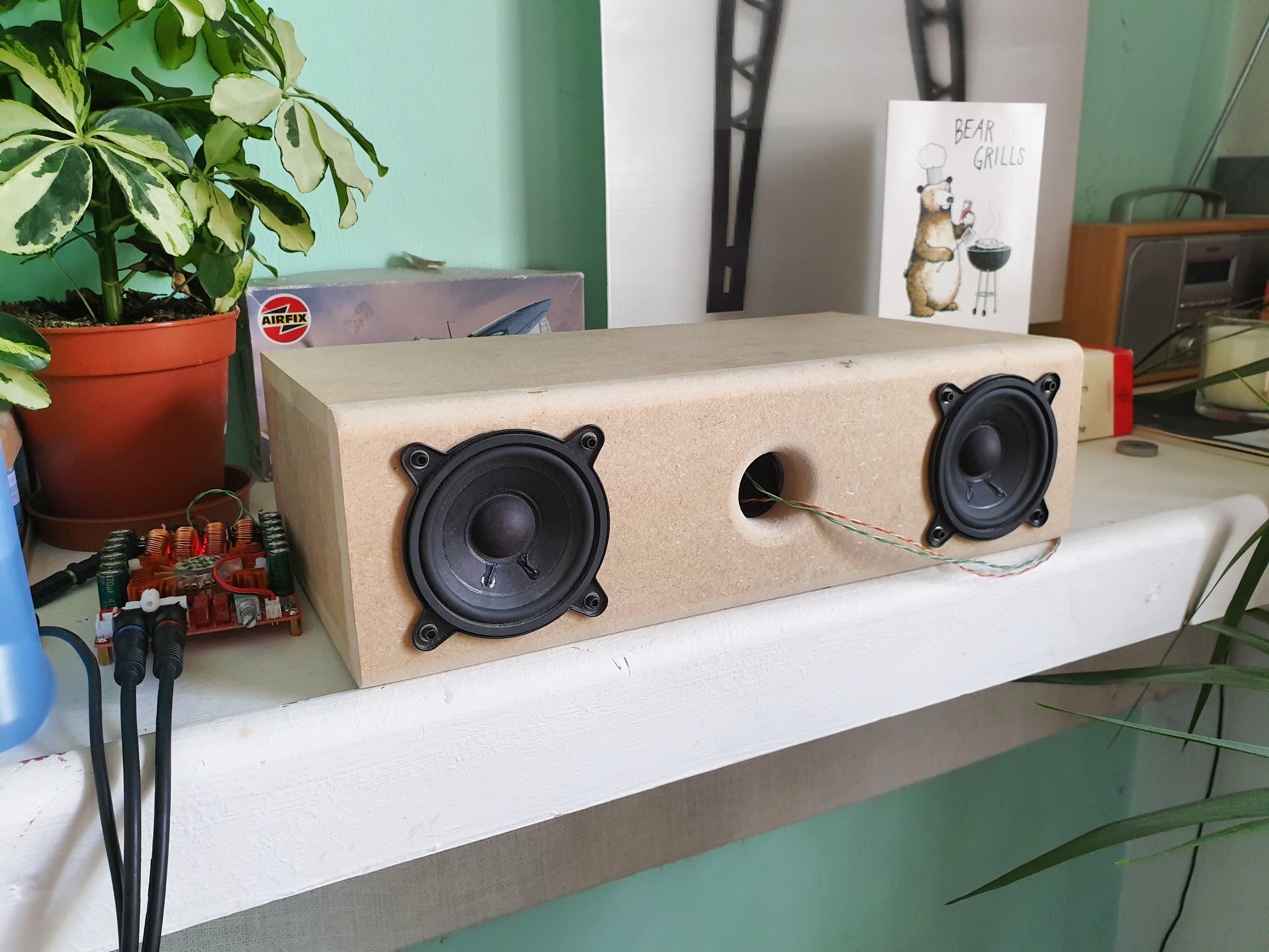
I am in the electronics phase of a bluetooth speaker build I am putting together. My aim is for limited bandwidth and SPL but smooth response between 70hz-18khz. With boundary gain I will get a little help on the low end.
I will be using an ADAU1701 Sure board for DSP and Faital Pro 3FE25 4ohm drivers.
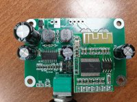
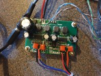
The board I have is a dual TPA3110D2 amp and during BT playback there is considerable noise masked by the program material. I can only assume that this is because of the gain setting but I am unsure how to go about fixing this.
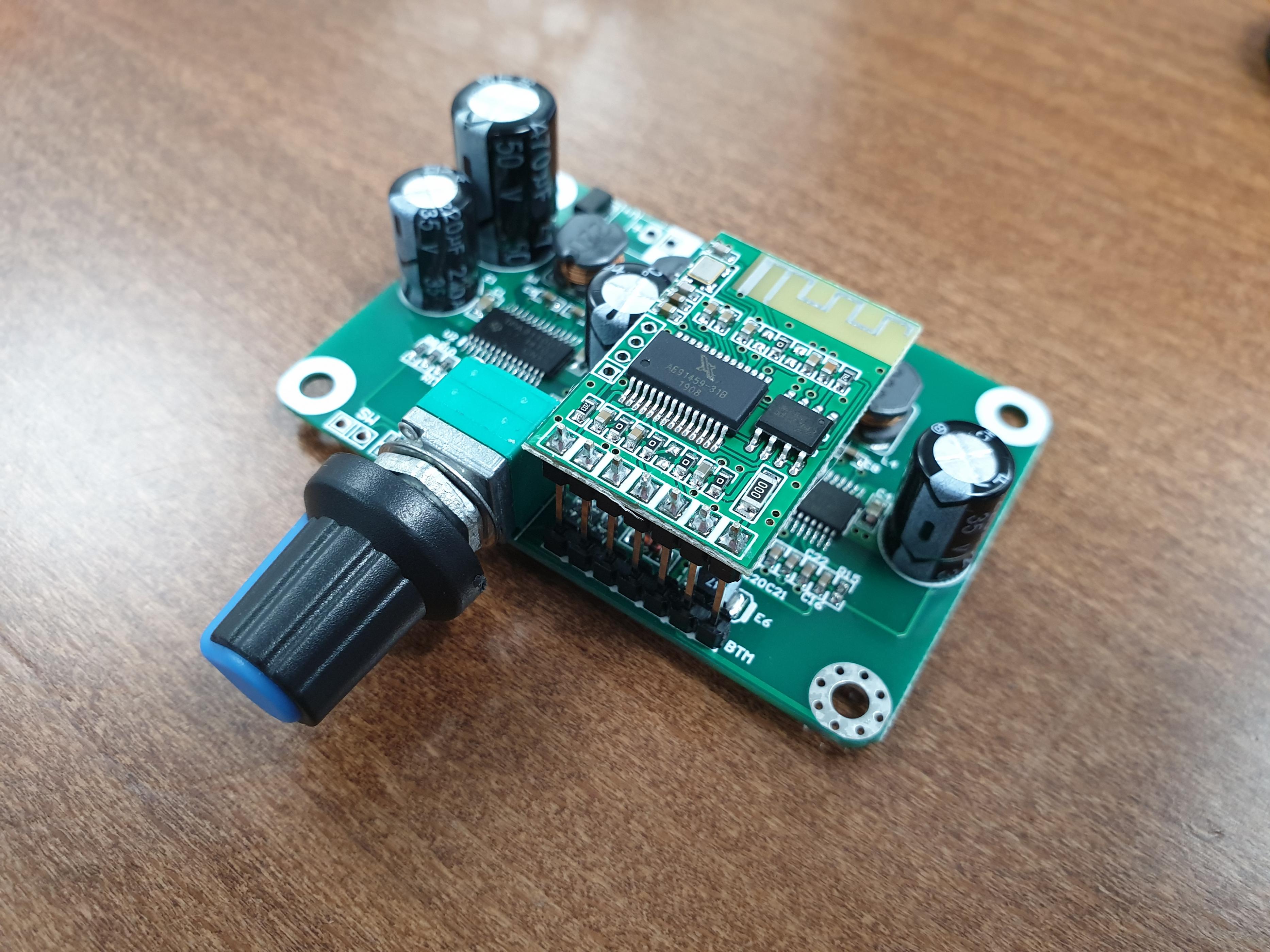
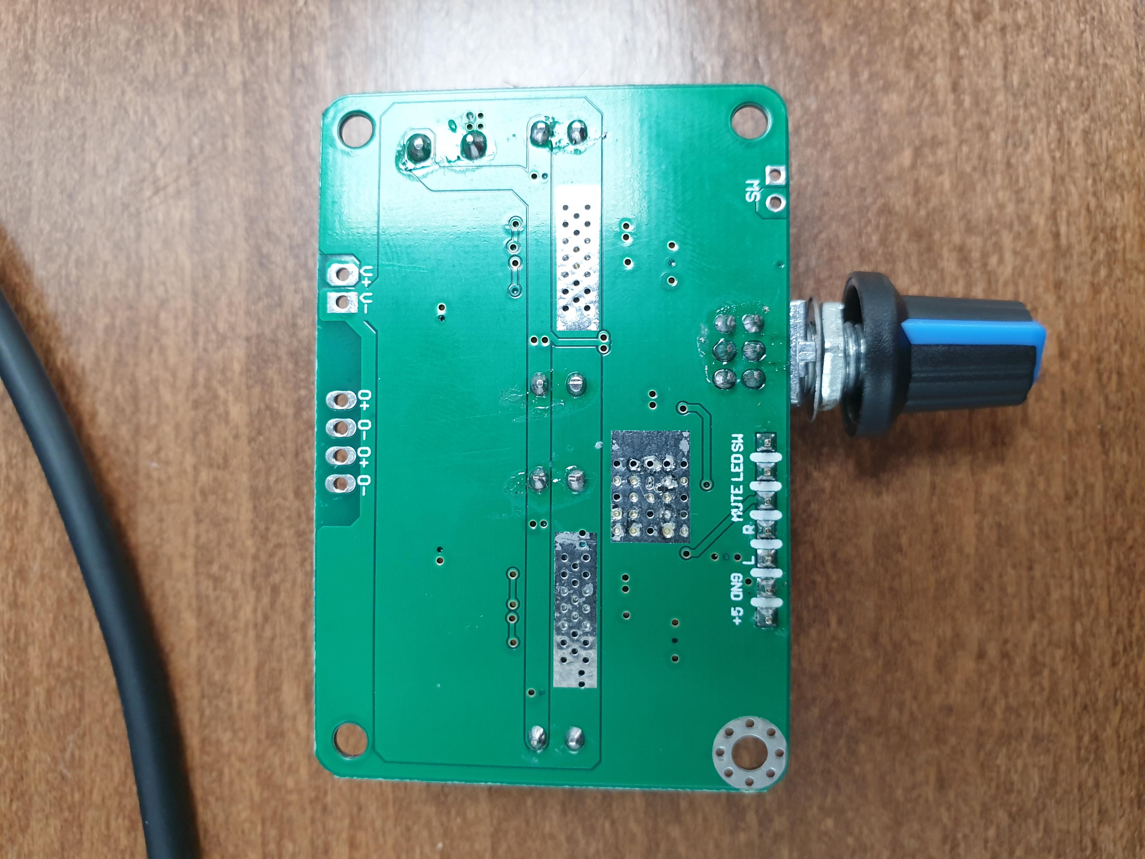
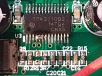
As pictured it appears pins 3, 4 and 5 are grounded - that is both the left differential inputs and a gain pin tied together. I guess this the inputs pins get put to ground as the right input is being used in this chip.

Would anyone kindly advise on how to change the gain setting for this board, please?
Also, I'm not 100% sold on this BT module on this board and have a couple others I would like to try. This board seems to have an auxiliary 5v out powering the BT board - does anyone think this will cause any issues?
In any event I aim to remove the BT module and route it to the ADAU1701 with an input selection switch to select between the BT module and a line in.
The BT module is switching the TPA3110D2 off an on when a signal is playing, will I be able to open this so that output is always on?
Also, the datasheet specifies a 470uf capacitor for power, would an upgrade here help bass?
Thanks in advance, I hope someone can shed some light on this board as I have found zero references to it other than 1 useless vid on YT and sale listings.
Cheers!
I am in the electronics phase of a bluetooth speaker build I am putting together. My aim is for limited bandwidth and SPL but smooth response between 70hz-18khz. With boundary gain I will get a little help on the low end.
I will be using an ADAU1701 Sure board for DSP and Faital Pro 3FE25 4ohm drivers.
The board I have is a dual TPA3110D2 amp and during BT playback there is considerable noise masked by the program material. I can only assume that this is because of the gain setting but I am unsure how to go about fixing this.
As pictured it appears pins 3, 4 and 5 are grounded - that is both the left differential inputs and a gain pin tied together. I guess this the inputs pins get put to ground as the right input is being used in this chip.
Would anyone kindly advise on how to change the gain setting for this board, please?
Also, I'm not 100% sold on this BT module on this board and have a couple others I would like to try. This board seems to have an auxiliary 5v out powering the BT board - does anyone think this will cause any issues?
In any event I aim to remove the BT module and route it to the ADAU1701 with an input selection switch to select between the BT module and a line in.
The BT module is switching the TPA3110D2 off an on when a signal is playing, will I be able to open this so that output is always on?
Also, the datasheet specifies a 470uf capacitor for power, would an upgrade here help bass?
Thanks in advance, I hope someone can shed some light on this board as I have found zero references to it other than 1 useless vid on YT and sale listings.
Cheers!
Attachments

Thanks man, any input would be appreciated. I just realised I need to have a go at probing and trying to put together a schematic.
Hi
it would be nice to post a link -seller of the board.
i can see its a dual chip TPA3110 set to PBTL
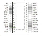
pin 14 is soldered over a 100kR to AVCC and this set the TPA3110 to the PBTL = mono configuration. at datasheeet figure 46 you see that.
Pin 3+4 are the pins for Left in and this are set to GND.
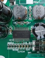
Gain (page 18-table2)
the gain selection on PIN 5 is set to GND = logical 0
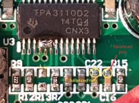
but the pin 6 (as i cas see at the pic, its over R11 marked 104= 100k) is set to logical high = 1
so your gain is 32dB...this is high. you have to cut the trace from pin 5 to the resistor R11 and solder a tiny connection to pin 4.--> Gain 0 (4) +Gain1(5) are logical 0
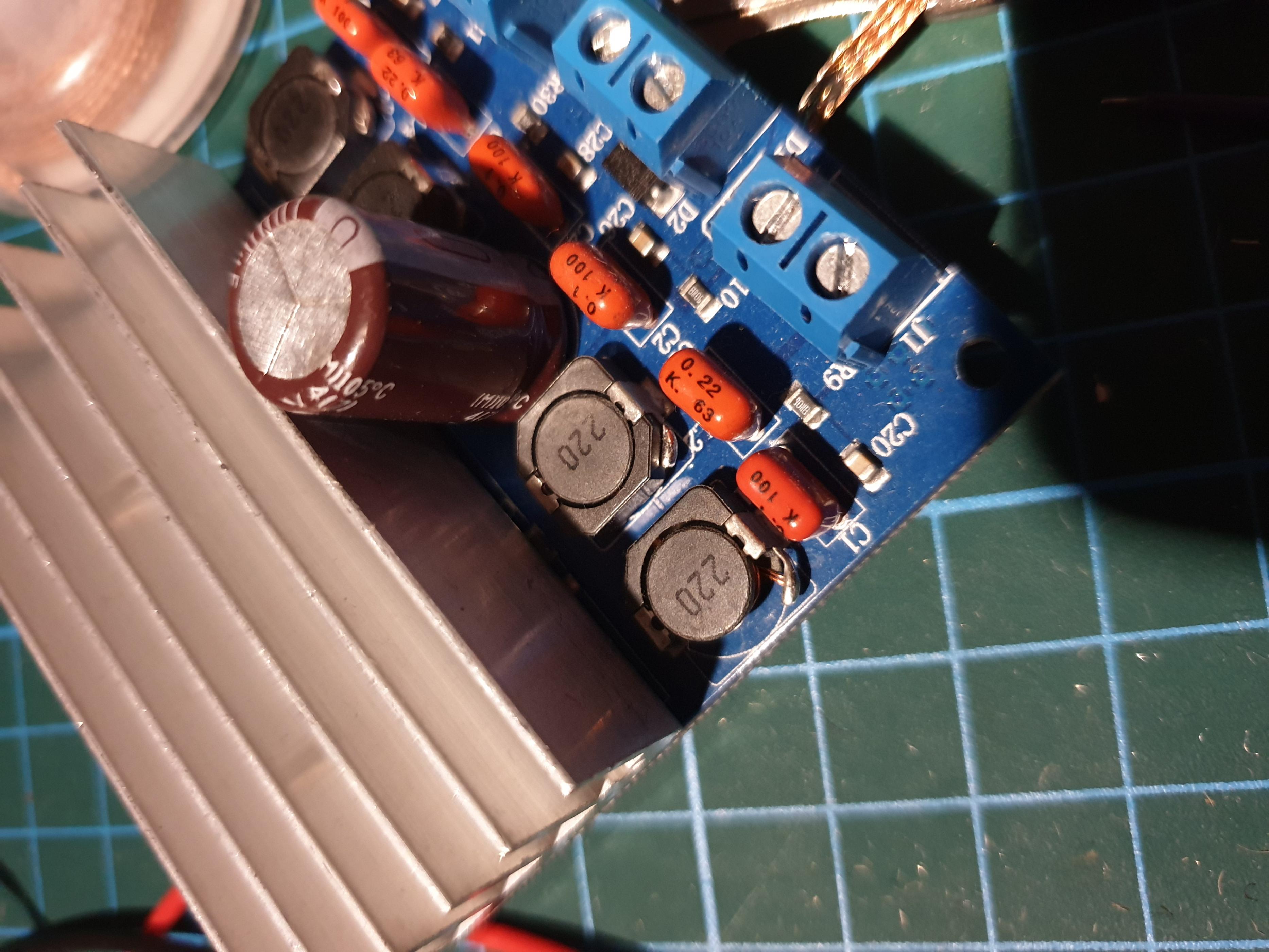
output filter coils are 22µH...at figure 40 there is no 22µH configuration. the minimim impedance for PBTL is 3,2R (chapter7.1)..keep ths for the 1 step
to be honest -i am not sure what happend here:
at pin 9 GVDD + pin 10 PLIMIT...the trace looks in between both pins.
as written in 9.3.4 there should be a resistor devider from GVDD (max7V) to GND to set the plimit
Add a resistor divider from GVDD to ground to set the voltage at the PLIMIT pin.
hopefully doc can re check my statements😉
chris
it would be nice to post a link -seller of the board.
i can see its a dual chip TPA3110 set to PBTL
pin 14 is soldered over a 100kR to AVCC and this set the TPA3110 to the PBTL = mono configuration. at datasheeet figure 46 you see that.
Pin 3+4 are the pins for Left in and this are set to GND.
Gain (page 18-table2)
the gain selection on PIN 5 is set to GND = logical 0
but the pin 6 (as i cas see at the pic, its over R11 marked 104= 100k) is set to logical high = 1
so your gain is 32dB...this is high. you have to cut the trace from pin 5 to the resistor R11 and solder a tiny connection to pin 4.--> Gain 0 (4) +Gain1(5) are logical 0
output filter coils are 22µH...at figure 40 there is no 22µH configuration. the minimim impedance for PBTL is 3,2R (chapter7.1)..keep ths for the 1 step
to be honest -i am not sure what happend here:
at pin 9 GVDD + pin 10 PLIMIT...the trace looks in between both pins.
as written in 9.3.4 there should be a resistor devider from GVDD (max7V) to GND to set the plimit
Add a resistor divider from GVDD to ground to set the voltage at the PLIMIT pin.
hopefully doc can re check my statements😉
chris
Last edited:
hi
i chekced the traces at the output pins to the coils....of the pic 4 in your first post. yes this looks ok.(according to DS figure 46 🙂
chris
i chekced the traces at the output pins to the coils....of the pic 4 in your first post. yes this looks ok.(according to DS figure 46 🙂
chris
Hi
Gain (page 18-table2)
the gain selection on PIN 5 is set to GND = logical 0
but the pin 6 (as i cas see at the pic, its over R11 marked 104= 100k) is set to logical high = 1
so your gain is 32dB...this is high. you have to cut the trace from pin 5 to the resistor R11 and solder a tiny connection to pin 4.--> Gain 0 (4) +Gain1(5) are logical 0
Thanks man, I will desolder the BT board tonight and take clear shot.
Just to clarify:
"you have to cut the trace from pin 6 to the resistor R11 and solder a tiny connection to pin 5.--> Gain 0 (5) +Gain1(6) are logical 0"
Pin 4 is one half of the balanced in.
Would it be sensible to desolder R11 and bridge the two gain pins at the IC?
uuups...i am very sorry man, exercise well done...😉
yes you are right!
yes you can desolder R11 and ground the gain pin.
Evening all.
Success! The gain is significantly lower. Thanks Chermann!
The noise that it was muting was interference by sharing the power supply - pretty crappy design. If the power comes from a separate PSU 5v charger the signal is pretty clean.
I have ordered some of the BA050 isolators for this however, I've unsure how they work internally. I hope they will.
I have checked the datasheet but there is no distinct mention of where I put the MUTE connection. It only seems to unmute when it is going to voltage. Any thoughts, people?
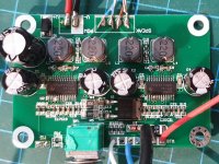
Here are shots of the board with my solder jobs which could definitely be neater but this isn't the final assembly...
Success! The gain is significantly lower. Thanks Chermann!
The noise that it was muting was interference by sharing the power supply - pretty crappy design. If the power comes from a separate PSU 5v charger the signal is pretty clean.
I have ordered some of the BA050 isolators for this however, I've unsure how they work internally. I hope they will.
I have checked the datasheet but there is no distinct mention of where I put the MUTE connection. It only seems to unmute when it is going to voltage. Any thoughts, people?
Here are shots of the board with my solder jobs which could definitely be neater but this isn't the final assembly...
Attachments
Hi
well done...🙂
the solders look ok....watch out about too much heat...at the tpa3110 chip i can see some heat event....use for smd 10W-20W with very small solder edge...
just be careful that at this tiny solder pads and cables no short happened.-->e.g. at your power V+ V-......keep the isolation
i never tried a BT board...so wait until doc has time to help you😉
chris
Last edited:
Thanks Chris, I'll keep that in mind!
In the mean time...
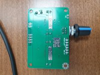
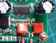
Balanced inputs for this chip:
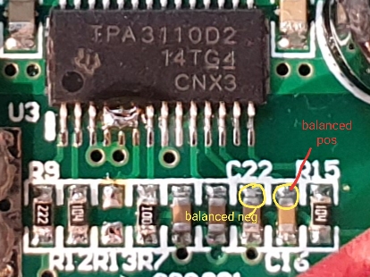
I believe in this image pin 11 (balanced neg) goes via C22 to ground and pin 12 (balanced positive) is the single ended input with a capacitor C16 beforehand. These are my access points for balanced but do I need a capacitor in front of the negative input as well or can I remove both c22 and c16 and go straight in to the balanced inputs without?
I read in the datasheet that gain settings effect the appropriate choice in capacitor input value but it is unclear if this is just for single ended input. Hmmmmmm.
In the mean time...
Balanced inputs for this chip:
I believe in this image pin 11 (balanced neg) goes via C22 to ground and pin 12 (balanced positive) is the single ended input with a capacitor C16 beforehand. These are my access points for balanced but do I need a capacitor in front of the negative input as well or can I remove both c22 and c16 and go straight in to the balanced inputs without?
I read in the datasheet that gain settings effect the appropriate choice in capacitor input value but it is unclear if this is just for single ended input. Hmmmmmm.
Attachments
I'm busy with family actually, sorry. Will be back tonight, until then keep it up.
BTW. PLimit don't need a resistor divider until you want to limit output power independently from supply voltage.
Eliminating BT noise with an isolated DCDC converter is asked a good idea when the connections are single ended (audio signal), just make sure you don't make up a new ground loop.
BTW. PLimit don't need a resistor divider until you want to limit output power independently from supply voltage.
Eliminating BT noise with an isolated DCDC converter is asked a good idea when the connections are single ended (audio signal), just make sure you don't make up a new ground loop.
@graham, desolder both caps and solder then standing up on the pads closer to the chip. Then wire your DSP outputs there.
@graham, desolder both caps and solder then standing up on the pads closer to the chip. Then wire your DSP outputs there.
Thanks for the input!
So the capacitors ARE needed before the input to balanced pins?
Thanks for the input!
So the capacitors ARE needed before the input to balanced pins?
no....... as i interpret the info by Doc.
desolder both caps and solder then standing up on the pads closer to the chip
your yellow circles on the pic
Last edited:
If you rely on the ADAU output coupling caps, then not. If not, then yes. 🙂 You may measure the DC-Bias as the DSP outputs with respect that GND. (No signal from DSP, idle)
Thanks guys.
I think I will desolder the caps as my soldering is not that delicate and solder on some larger caps donated from this broken amp board. I think they are compatible and will make the process a whole lot less rage inducing.
Now that the gain has been lowered the datasheet recommends changing the input cap value and as per the example circuit with 60k input it suggests 0.15uf. Is this the case? I believe the input caps at the moment are 1uf. Can anyone clarify please?
As for the 'mute' pin? Well, that just goes to voltage as per the example circuit in the datasheet. I should have realised.
Attachments
good morning
use the red caps with the label "K100" and it is fine. normally the caps have a tolerance of +/-20%...so do not care if you use 0,15 or 0,1
the formula what you mentioned is the formula (ds 10.2.1.2.2.) for the fg of the low bass filter 1st order..... that means with 60k and the 0,1µF you get about 26,5Hz and its low enough😉.
Tiefpass Filter mit RC-Glied, passiv, 1.Ordnung
chris
Thanks for the help so far, people!
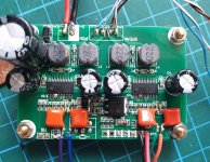
Right, so I made some progress yesterday and managed to:
1. Changed the large power supply capacitor from 50v/470uf to 35v/1000uf. This had zero effect that I could measure using the bass port as a before and after test. Having reread the DS it suggests that 220uf is enough so I guess 1000uf is overkill. Thoughts anyone?
2. Removed the surface mount input caps for the balanced pins - success! I now have a balanced link from the ADAU1701 to the TPA3110D2 - Absolutely brilliant as I can now power the board from the amps auxiliary power supply without issue. This was not as hard as I thought it would be and it helped to have removed the redundant potentiometer beforehand. It is the smallest soldering job I have done so far so isn't perfect and looks better in the flesh than my images.
I have since added some heat shrink for isolation and some silicone to keep the caps in place.
3. Soldered the 'mute' connection which is pin 1 to the input voltage. However, I am starting to think I should just bridge pins 1 and 2 instead?
Everything seems to be working fine but there is one issue if anyone cares to speculate on the cause?
With bass heavy tracks or, TBH, most tracks with a strong bassline there is a noticeable dip in overall output energy (if listening for it it is very apparent, if not you might not notice) . During vocal only sections of the song the level goes up, much like a typical studio compressor. It isn't always apparent which makes me think it is frequency dependent. Ie, when low-low bass is in a track it struggles slightly.
Would this have anything to do with the changed capacitor and recharge time considering it is a larger value? I have had some odd behavior from the Sure ADAU1701 board when measuring and it flat lining when I apply internal gain however, I have removed this extra gan and I am still encountering this issue.
This is getting exciting!
Attachments
Last edited:
Hi Graham
really nice job !🙂
point 1
1000µF/35V cap-its sufficient if the cap is an low esr type. why? as i learned from doc, voltwide, irrebeo, abrax... in a class D amp the low ESR/ESL of a cap is important on the rails supply pins. so therefore a big fat electrolytic might be not the best solution--> use caps which are normaly in smps-they have low esr/esl because smps = Class D amp
so check the other caps with a LCR(C) meter - ESR should be about 20mR -470µ -1000µF is enough
this could be the reason of some bass "problems"... but normaly the power supply is the bottel neck of "weak" bass. normally bricks - LED bricks are not able to push fast enough current--> caps should deliver it-......bad caps = high ESR= low current availability....etc...so if you have a strong enough power supply your caps have nothing to do😀
chris
Last edited:
- Home
- Amplifiers
- Class D
- TPA3110d2 BT Board Fixes?