I have got my new board V1.07 with display.
Unfortunately I can not get a signal when I feed a digital signal over SPDIF.
For what the VOL jumper in the middle of the board is used?
Do I have to see the LOCK LED when input signal is detected?
Unfortunately I can not get a signal when I feed a digital signal over SPDIF.
For what the VOL jumper in the middle of the board is used?
Do I have to see the LOCK LED when input signal is detected?
Hi Ampi,
To receive SPDIF you have to put the dac into that mode. If not using the controller, I think J2 selects SPDIF mode.
The volume jumper is to use if you don't use a volume pot. It keeps inadvertent noise pickup from affecting the input signal pin. IIRC, center pin grounded gives maximum volume if using the jumper. Increasing positive voltage at the center pin increases volume attenuation (it kind of works backwards from the way people sometimes expect).
Let's hope then the AKM evaluation board comes at a reasonable price and is "mod flexible" ;-)
From looking at the AK4499 evaluation board documentation, it appears that most of the things we might want to mod are either not included on the board (power supplies, differential-summing), or can be bypassed (AKM's discrete 'AVCC' voltage regulators). Also, the eval board is constructed in a motherboard-daughterboard configuration. Presumably, the daughterboard with the dac chip on it could be used separately if desired. However, it does look like the I/V converters (OPA1612) are going to be on the daughterboard, meaning that changing the design there might require making a custom development board. Don't expect it will be a problem for me, at least initially. At some point my high end designer friend may want to try a discrete output stage of his own design, in which case we would have to see if that would be a problem using the stock evaluation board.
Hi Ampi,
To receive SPDIF you have to put the dac into that mode. If not using the controller, I think J2 selects SPDIF mode.
The volume jumper is to use if you don't use a volume pot. It keeps inadvertent noise pickup from affecting the input signal pin. IIRC, center pin grounded gives maximum volume if using the jumper. Increasing positive voltage at the center pin increases volume attenuation (it kind of works backwards from the way people sometimes expect).
Thanks Mark for the tip! Without the display and the jumper J2 set spdif is running🙂.
That is strange because on the display I can change the sources and the volume. So I have to check what is wrong wit my display. Can someone confirm that switching the inputs by the display works?
Will the evaluation board be publicly announced?😕Do you perhaps have a link for the evaluation board? I couldn't find it on the AKM site :-(
zek,
I'm sure it will be announced and everyone around here will know when they start to be available for sale. The eval board documentation I have came from an AKM distributor and is only Rev. 0, so who knows how Rev. 1 will look. Boards are expected to be available maybe in June or July, but we will have to wait and see if they are late or not.
I'm sure it will be announced and everyone around here will know when they start to be available for sale. The eval board documentation I have came from an AKM distributor and is only Rev. 0, so who knows how Rev. 1 will look. Boards are expected to be available maybe in June or July, but we will have to wait and see if they are late or not.

Those good value KEMET DC Link films caps worked well, not much to say other than 1 40uf noticeably improved SQ beyond what a large amount and variety of electrolytic and small film caps could.
Those good value KEMET DC Link films caps worked well...
Thank you for the update!
Could you please post the part number again for people who may want to give them a try?
May I ask if anyone has gotten started yet with Arduino or other means for accessing registers?
Hi Mark,
I was trying to start it when my sparkfun voltage level shifter chip just slides out of place!! Maybe a faulty one. Meaning to try soldering them in place but have not got to it yet.
Regarding the dac register program you kindly attached in earlier post, it describes wiper, momentary pushbutton and putty. Do we need those? Not that I cannot use them.
By the way, I have changed the balanced out resistors from 5k to 221ohm as suggested. The sound is even cleaner than rca. Am liking it a lot.
Regards & Cheers,
Kay.
I was trying to start it when my sparkfun voltage level shifter chip just slides out of place!! Maybe a faulty one. Meaning to try soldering them in place but have not got to it yet.
If the chip itself was not properly soldered to the board then the board they sent you is defective. You might be able to solder the chip back on if you solder all the pins at once using some extra flux (if available) the then use solder wick to remove excess solder shorting between the pins and solder pads. If you try that don't use too much solder or it can get down in deep where you can't wick off the short circuits.
Regarding the dac register program you kindly attached in earlier post, it describes wiper, momentary pushbutton and putty. Do we need those? Not that I cannot use them.
No need for those things. They were meant to be options, but I didn't use them, or haven't yet 🙂
By the way, I have changed the balanced out resistors from 5k to 221ohm as suggested. The sound is even cleaner than rca. Am liking it a lot.
It means there is some problem, but not necessarily one that has to be fixed. Balanced out might be the best fix that is practical in some cases. Could be with grounding and AC power between the dac and your power amp. Could be your power supply for +-15v is not clean enough yet. Do you have any film caps on it? If so, then its probably not a problem there.
Last edited:
Hi Mark,
I do use a collection of jantzen & dayton film caps 45.84uf per line for +-15v. Details at ES9038Q2M Board. They improved the sound a lot.
Regarding the ground connections, I used ground connections for all lines. These includes lm317/337, two lt3042s, two lt1763s. Becomes confusing, Diagram attached below.
Kay.
Attachments
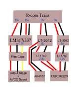
Regarding the ground connections, I used ground connections for all lines. These includes lm317/337, two lt3042s, two lt1763s. Becomes confusing, Diagram attached below.
The ground diagram raises some concerns. It looks like you have two red lines going to the dac chip from the same upstream regulator that powers AK4137, but no black ground directly to the dac chip from there. That can't be right.
Also, where the AK4137 and dac chip share grounds from the shared regulator, you may find sound quality is improved by using one or two ferrite clamps on the AK4137 ground wire. That will help keep I2S ground currrents from partially returning through that ground path between AK4137 and the dac chip.
Hi Mark,
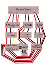
Sorry for the poor diagram. Corrected one attached below.
What kind of ferrite clamps? Like this is ok? https://www.amazon.in/Ferrite-10-Pack-Suppressor-Filter-Antenna/dp/B015E8DHC0.
Also included signal lines in the corrected diagram.
Regards,
Kay
Sorry for the poor diagram. Corrected one attached below.
What kind of ferrite clamps? Like this is ok? https://www.amazon.in/Ferrite-10-Pack-Suppressor-Filter-Antenna/dp/B015E8DHC0.
Also included signal lines in the corrected diagram.
Regards,
Kay
Attachments
- Home
- Source & Line
- Digital Line Level
- ES9038Q2M Board