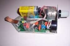
I built one several years ago: it is a ~100dB highly selective amplifier followed by a mixer with a 53Hz local oscillator.I am thinking of using a hum sniffer; A small wire loop, to locate humming fields.
The result is further amplified, low-pass filtered and drives a LED and also modulates a buzzer oscillator.
A dual logarithmic pot controls the gain at two different places of the amplification chain, to get enough dynamic range.
With the gain pushed to the max, it can sniff a 100kV power line more than half a kilometer away!
The sensor is an ordinary drum core inductor, tuned approximately to 50Hz by a capacitor (the Q is very low, something like 1 or 2, IIRC).
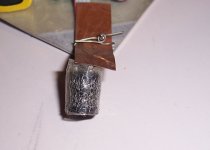
It is shielded by a mesh-screen:
It is a useful piece of kit
Attachments
Nice, a very elaborated sniffer.
I am thinking of something much simpler: A loop of wire at the input of an oscilloscope at full gain, directly on the input ( no x 1/10 probe ).
BOM: 1 BNC connector, 2 metre shielded cable, 1 small coil ( few turns, 10mm diameter... like a RF choke )
I am thinking of something much simpler: A loop of wire at the input of an oscilloscope at full gain, directly on the input ( no x 1/10 probe ).
BOM: 1 BNC connector, 2 metre shielded cable, 1 small coil ( few turns, 10mm diameter... like a RF choke )
Last edited:
Toroids have to be closed in it's own magnetic and electrical isolated enclosure, or else the whole case works as good short wind (winding). The main part of that problem can be a screw you used to fix (fasten) toroid tansformer - they "like" ferite (steel) screws, nuts and washers. Use only stainless steel screws (nuts etc.) in low-noise designs (they are usually non-ferite) and make some electrical isolation between screws and enclosure, and make some distance between transformer and metal case surface (at least 10-20 mm or more).I had a very confusing experiment.
Very sensitive microphone préamplifiers in a ALUMINUM enclosure with a PSU inside using a toroidal for +15v -15V +48V.
All went fine testing with microphones, until, I closed the top of the box.....Hum came in.
I don't like toroids in low-noise designs at all because they have several times larger capacitance between primary and secondary than other types. So all secondary circuits have much "better" connection with mains voltage. If we have two or more device - they will have large parasitic connection (thru this capacitance). This means the same noise and hum.
Last edited:
Why would a transformer without at least one screen winding be used in "an ultra low noise instrumentation amplifier" design? Either the designer hasn't done their home work, or penny pinching I guess.I don't like toroids in low-noise designs at all because they have several times larger capacitance between primary and secondary than other types.
Indeed, the transformer quality was overlooked.
The design objective was low noise, thanks to an extremely good low noise front end and balanced circuit giving a best Comon Mode Rejection.
This is why, I look for a quiet transformer. Either I can make the present one quieter or it will be replaced.
The design objective was low noise, thanks to an extremely good low noise front end and balanced circuit giving a best Comon Mode Rejection.
This is why, I look for a quiet transformer. Either I can make the present one quieter or it will be replaced.
With the average scope having a max sensitivity of ~1mV/div, the fields intensities you will be able to detect at 50Hz are going to be horrendous from a sensitive electronics POV.Nice, a very elaborated sniffer.
I am thinking of something much simpler: A loop of wire at the input of an oscilloscope at full gain, directly on the input ( no x 1/10 probe ).
BOM: 1 BNC connector, 2 metre shielded cable, 1 small coil ( few turns, 10mm diameter... like a RF choke )
Could be good for very rough, short distance tests close to the perturbation source, but for actual in-situ eval, you will need at least 60dB of gain in front of that.
I'll try my simple way:
With direct input instead of usual probes I gain 20dB
With 10 times more turn I gain 20dB
I can try as a coil one from a 220 Volt relay, it has a hell of turns of thin wire.
Who knows how to compute the voltage given by the coil from the number of turns the coil diameter and the magnetic field ?
With direct input instead of usual probes I gain 20dB
With 10 times more turn I gain 20dB
I can try as a coil one from a 220 Volt relay, it has a hell of turns of thin wire.
Who knows how to compute the voltage given by the coil from the number of turns the coil diameter and the magnetic field ?
Last edited:
To power the instrumentation amps, bring in DC rather than AC. Build the AC-to-DC power supply in a completely separate, quadruply shielded enclosure, at least 15 meters away from the instrumentation amplifiers. Run DC cables from the PSU to the inamps. Don't forget to wrap ferrite core/clamp noise stoppers around the cable, every meter or so. Mouser part number 875-28A2025-0A0 is a possibility.
On the way to gravitationnal waves detection, however my amp is not ready yet, it needs a lower equivallent input noise and liquid nitrogen cooling 😉To power the instrumentation amps, bring in DC rather than AC. Build the AC-to-DC power supply in a completely separate, quadruply shielded enclosure, at least 15 meters away from the instrumentation amplifiers. Run DC cables from the PSU to the inamps. Don't forget to wrap ferrite core/clamp noise stoppers around the cable, every meter or so. Mouser part number 875-28A2025-0A0 is a possibility.
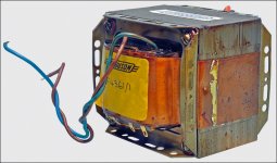
Getting back to shielding transformers, to give you an idea what is possible with a copper flux band, Silicon Chip (SC) magazine, when they did some 2012 articles on using their Ultra-Low Distortion Mk3 amplifier modules in Altronics’ stereo kit, found that Altronics had provided a non-shielded 300VA transformer (it really should have been a 500VA tranny, but that’s another story!).
They elected to put a DIY 0.5mm copper sheet flux band around it, held in place by a 120mm stainless steel screw (Jubilee) clamp. This improved the signal to noise ratio by 7dB in one channel (closest to the transformer), and 11dB in the other channel, so was well worth doing. See below for a photo.
They used successively smaller paint tins to wrap the copper sheet around, until it fitted the circular transformer, then put the clamp over it to hold it in place.
Regards,
Don
Attachments
Last edited:
I don’t know why the copper flux bands work, but have heard it shorts out the flux leakage. Copper flux bands were widely used in EI transformers for Australian amplifier kits in the 1970’s and 80’s, the most famous of which was the ETI Series 5000 and the upgraded AEM 6005, which used twin 200VA transformers to power a 150W/4Ω stereo amp. Both were designed by Dr David Tilbrook, who’s a DIYAudio member, although he later went on to lecture in physics at various universities. The flux bands made them much quieter than the alternative c-core transformers from another manufacturer.
But as you can see, a 7 or 11dB noise reduction from a copper flux band proves it works fairly well, as SC proved, and it’s a lot cheaper than mu-metal. They did mention that the three Australian toroidal manufacturers (Tortech, Harbuch or Dyne Industries) would make custom shielded transformers when asked. In fact, an SC reader built himself a ULD Mk4 stereo amp, complete with a custom shielded Tortech 500VA transformer, and sent in a picture of it, and it certainly had some sort of metal shield around the outside of the transformer – they also put a foil screen between the primary and secondary windings for him.
However, as a cheapskate, I’ve got twin 300VA Dick Smith Electronics transformers I bought at about half price on Ebay after DSE stopped supplying hobby electronics components, to power my SC200 modules, and I’ve got some 0.3mm (easier to bend) sheet copper ready to shield them with copper flux bands! I've also bought a very large case with heatsinks from a Chinese seller, and I couldn't believe the quality - I'm not sure how they do it at the price, but I might make some modifications to the case, such as blanking out the + and - symbols next to the speaker terminal holes - I suppose Chinese metal workers don't know much about AC!😀
Last edited:
Apparently the copper flux band acts as a shorted turn to the flux leakage, and sets up eddy currents in opposition to cancel the flux leakage out. SC did say that you should clean the copper so that the overlapping bits electrically connect. With EI cores, they can be soldered, as shown here.
Attachments
If some is good then perhaps more is better.
Why assume that N=1 copper bands is the optimum number? Why not install three or four of them, layered one atop the other?
A visit to a plumbing supply house may discover a round steel pipe of exactly the correct diameter to make your own magnetic shroud, which goes over the transformer plus N=3 copper bands. It could save you $44 as demonstrated here. Cut out a flat circular plate of steel to make an end cap, weld it on (or pay a student welder two six-packs of the good stuff to weld it on), and Bob's your uncle.
_
Last edited:
We had some hum reduced with an aluminum part as a wall between the transformer and the mic preamps.
Non magnetic material has, indeed a shielding effect, that I did not expected before it was tried.
It is interesting to experiment with Copper, Aluminium, Steel bands around, see about shorting as a one turn winding, see about caps under and above.
Non magnetic material has, indeed a shielding effect, that I did not expected before it was tried.
It is interesting to experiment with Copper, Aluminium, Steel bands around, see about shorting as a one turn winding, see about caps under and above.
Shielding by conducting rather than magnetic materials is possible, but at low frequencies like 50 or 60Hz, it is not very efficient.
The skin depth (~indicative of a 1/e attenuation) is shown in this graph:
Skin effect - Wikipedia
Around 12mm for Al
The actual effect will vary a lot with the actual, physical configuration, as with all magnetic-related problems.
Often though, most of the troubles are caused by mains harmonics, because when the magnetic flux escapes from the core due to saturation, the harmonics are predominant.
As these harmonics are normally odd-ordered, this means that the first culprit will be 150/180Hz, somewhat easier to eliminate than the base 50 or 60Hz.
How come the transformer can work correctly with this one turn winding SHORTED. Usually winding turns shorted, induces overheating if not the death of the transformer.Apparently the copper flux band acts as a shorted turn to the flux leakage, and sets up eddy currents in opposition to cancel the flux leakage out. SC did say that you should clean the copper so that the overlapping bits electrically connect. With EI cores, they can be soldered, as shown here.
Looking more carefully, I see it is not installed like an additionnal one turn winding. It is a shorted one turn for the stray field only.
Last edited:
In the N more than 1, there is an alternative to N bands layered one atop the other:If some is good then perhaps more is better.
Why assume that N=1 copper bands is the optimum number? Why not install three or four of them, layered one atop the other?
A visit to a plumbing supply house may discover a round steel pipe of exactly the correct diameter to make your own magnetic shroud, which goes over the transformer plus N=3 copper bands. It could save you $44 as demonstrated here. Cut out a flat circular plate of steel to make an end cap, weld it on (or pay a student welder two six-packs of the good stuff to weld it on), and Bob's your uncle.
A N turn winding shorted. Why not install a one layer winding made of heavy gauge copper wire.
It is not clear wether the shieding effect comes from eddy curents or a shorted winding acting on the flux leak.

- Status
- Not open for further replies.
- Home
- Design & Build
- Parts
- Low noise PSU transformer