quite simple load
8ohm 15" woofer jbl 2226
16ohm compression driver jbl 2446
crossover at 800Hz
8ohm 15" woofer jbl 2226
16ohm compression driver jbl 2446
crossover at 800Hz
It should work but the curves/characteristics are different and the circuit has to be adjusted for it.
Higher Yfs brings nothing good here by itself.
Anyway, you are free to experiment and see/hear what you get...
Higher Yfs brings nothing good here by itself.
Anyway, you are free to experiment and see/hear what you get...
Last edited:
juma: For the amp you put in post #164 (thank you for that) can you think of any reason to not use a cap multiplier PS like you posted for Cubie3, except it will be single rail only?
No reason at all.
Only thing you lose is 4V of power supply voltage.
And don't forget to use R14 ( it can be even lower, down to 100R, depending on how leaky the coupling cap is).
Only thing you lose is 4V of power supply voltage.
And don't forget to use R14 ( it can be even lower, down to 100R, depending on how leaky the coupling cap is).
Hello Juma,regarding the small preamp i attach,you specified Q1 as BF245C and R8 as 150Ohm in order to have a drain current of about 9.7mA. I dont have BF245C but i have 2 pieces BF245B that have a matched idss of 8.8mA.Can i use these instead of BF245C and what changes do i have to make?Thank you!
Attachments
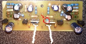
Maouna, I would not recommend that schematic. There is a better one. I attach the schematic, layout (100 x 32 mm, copper side view) and picture of the test module.
It's about 6 dB gain. For 12 dB gain change R5,R25 to 10k. The value of R3,R20 will set the MOSFETs' Id to 12-15ma (that's what we want) - you measure it as a voltage drop over R11,R18.
It's about 6 dB gain. For 12 dB gain change R5,R25 to 10k. The value of R3,R20 will set the MOSFETs' Id to 12-15ma (that's what we want) - you measure it as a voltage drop over R11,R18.
Attachments

Last edited:

Because the other one is better. The one from post #209 will work OK - use those BF245B that you have (Idss=8.8mA) without source resistor (R8,R17) or a very small one (10R) and adjust the value of R3,R21 so that you get half of the regulated power supply voltage at the MOSFET's drains (Q2,Q3).
I am almost done with the preamp of post #1 but i have question.
I see a resistor on the mini PCB on which BF862 is soldered.Does this resistor connects to the gate of BF862?
I see a resistor on the mini PCB on which BF862 is soldered.Does this resistor connects to the gate of BF862?
Attachments

Last edited:
For the psu section i am going to use a shunt psu posted by Juma, with 24Vac transformer (35V after rectification). the current source fet bf862 has to be changed to something with higher Vds than 35V.What do you suggest? I have 2SK170,BS170.
Attachments
Is the BF861B a suitable replacement for the BF862? What about any of these other jfets at Mouser?
JFET N-Channel SMD/SMT RF JFET Transistors | Mouser
What's the ideal jfet Idss for the circuit in post #1?
I would like to build it like the original circuit.
Are there any changes to the circuit in post #1?
I want to drive an F4 and MoFo power followers.
Thanks,
Vince
JFET N-Channel SMD/SMT RF JFET Transistors | Mouser
What's the ideal jfet Idss for the circuit in post #1?
I would like to build it like the original circuit.
Are there any changes to the circuit in post #1?
I want to drive an F4 and MoFo power followers.
Thanks,
Vince
It's a gate stopper. It doesn't make a difference here because R3 (22k) does that job already....Does this resistor connects to the gate of BF862?
2sk170 or 2sk246 (any grade will do)....bf862 has to be changed to something with higher Vds than 35V.What do you suggest? I have 2SK170,BS170.
BF861B with Idss >= 12mA will do OK.Is the BF861B a suitable replacement for the BF862?
Got no time to browse through all those datasheets but you should look for parts with high gm and linear transfer curve. Although, with some effort, many will work OK.What about any of these other jfets at Mouser?
12-15mAWhat's the ideal jfet Idss for the circuit in post #1?
I don't remember - did many different stuff since then. Maybe you should search/browse through thread(s).Are there any changes to the circuit in post #1?
12-15mAIs Idss of 14 ideal?
Thanks for the suggestions.Juma,do you have any other shunt PSU like the one with TL431 but with 48V output and the same noise suppression results??.My load current will be max 22mA
If i want to put a coupling capacitor between input volume pot and R3,where should i connect the + of the 10u electrolytic capacitor?(i only have 10uF/50V electrolytic nichicon FW series)
Regarding the 470ohm gate stopper resistor,should i ommit it ithis case? i have already made space for the resistor in my small pcb.
Regarding the 470ohm gate stopper resistor,should i ommit it ithis case? i have already made space for the resistor in my small pcb.
Attachments
- Home
- Amplifiers
- Pass Labs
- Gyrator loaded Son of ZV9/F3