Hi Scott, happy to:
Qes = (2Pi*Fs*MMs*Re)/(Bl^2)
The Re is the DC resistance of the voice coil. If the Re changes by 10%, such as adding an output impedance (of the amplifier), then it supposedly has a DF of 10. But in actual fact, the Qe has increased by 10%. The amplifier decreases damping, does not increase it.
If you increase the loss the Q of the system is decreased this is just plain physics. Let's just forget it you clearly don't understand the basics. How about amplifier output impedance = 0 or infinite?
Besides, the amplifier can only see one impedance at a time (at any one frequency). It cannot see its own output impedance as separate to the Re of the driver. Hence the divide between the two is not something that the amplifier can act upon.
You're back to the nonsense.
Last edited:
Yes of course generator effect in operation.Now that I would like to see. I assume this will all work its way back to what is and what is not current drive. There is actually a trivial experiment to show damping on a speaker, displace the cone and measure what happens when you suddenly release it with the voice coil open and with it shorted. They are different.
What is the optimal loading for critical damping ?.
Dan.
Hi Scott.No it isn't, I assume you are preparing a Physics Letters paper to present these extraordinary results.
I am doing measurements now and getting clear results, 70dB or so down but showing changes in noise floor and dynamic noise above noise floor for USB SC direct loopback, amplifiers are worse/different and are next round of measurements.
In drawn wire there is inherent distortion/dislocation of metal crystals/boundaries and this is a standard current noise producing mechanism.
The orientation of these discontinuities could confer 'directionality' in wires with cables having the further complication of insulations characteristics.
Yes wire noise is very low but wire/cable noise does drive/excite downstream noise mechanisms, same as any conductor or conductive component.How much do you think is the noise contribution of a single wire in a preamp, in front of the active devices ? Please, be serious..
What are the other parameters ? (i used the word 'impedance')
I am doing testing/measurement now of excess noise and I will extend this to cable insulations and directions in due course.
I am interested to hear Ed Simon's wire/cable findings...Ed ?.
Dan.
If you increase the loss the Q of the system is decreased this is just plain physics.
What damping does is not that hard to understand. So what is it that I said that is incorrect. Correct me and I will thank you.
Let's just forget it you clearly don't understand the basics.
I thought insults were against the rules?
And you are incorrect to boot.
You're back to the nonsense.
Scott, once again, insults like that are not acceptable.
I quote the highest living authority on the subject, quote him very accurately, and you call that nonsense? Then quoting Einstein would also be nonsense? Please address the subject, that an amplifier cannot add damping, the output impedance can only erode damping. Is that not a correct statement, yes or no?
Damping is not that hard to understand. But it seems the effort to understand damping in speakers is hard for some. I can't do much about that.
Everything I have said in the last few posts are solidly based on science.
Have a good day!
.
Joe, I am not a speaker guy, but I wonder if you can clarify something for me. I could see that adding amplifier output impedance in series with voice coil resistance could result in a net decrease in lossyness (and increased Q) as compared to a perfectly shorted voice coil, but not to an open voice coil, is that correct?
I quote the highest living authority on the subject, quote him very accurately, and you call that nonsense?
.
Appeal to authority? Joe the effects when you drive a speaker from a high impedance vs. a low impedance are well documented ad nauseum all over the web. I've visited your physicist friend's web site when he talks EE it is full of mis-conceptions and just plain wrong stuff.
And please your ideas are in my opinion nonsense that is not a personal attack.
Last edited:
And please your ideas are in my opinion nonsense that is not a personal attack.
You went a lot further than that... be honest about that, OK?
Please Scott, I am at a total loss to understand you, so let us leave at that. I can only scratch my head and ask "why?"
Joe, I am not a speaker guy, but I wonder if you can clarify something for me. I could see that adding amplifier output impedance in series with voice coil resistance could result in a net decrease in lossyness (and increased Q) as compared to a perfectly shorted voice coil, but not to an open voice coil, is that correct?
Thank you for asking.
I hear the "open circuit" argument all the time. It is one of those arguments that seems so convincing. Speak to speaker guys about that, have a chat with them and you would be struck by two things. 1) They pretty much never speak about Damping Factor, but they sure speak about damping all the time. 2) They think of the alignment of the box and driver, as to what wholly defines the damping of the whole system. They may not express that in those precise words, but that defines their whole attitude. So it is a case of "it's the alignment, stupid."
The "open circuit" argument does not work for a very simple reason, the value of electrical Q depends on there being a circuit formed. It is the default position for the measured Qe of the driver, it is that of a circuit that is completed. So that is the starting point, from this point, adding any value to Re will erode and if eventually it becomes an open circuit, there will be zero electrical damping. Because there will cease to be a circuit.
Small's equation that he alerted me to, explains that is what is happening. Pay around with that equation and you get it. The logic is irrefutable.
So... to make the starting point an "open circuit" is not how this works.
But of course, the interface is more complex than that and if I elaborate I will be accused of making 'claims' when in fact I am reporting facts. Did you note that i slipped in a little remark and wondered if anybody would take me up on it and would be sternly 'corrected' on my delusion or whatever, not read any EE books (which I have of course) and other condescending chatter. But here goes:
I mentioned that you can cancel out the output impedance of the amplifier.
So far nobody took the bait. But that statement is true, indeed you can define circumstances where the voice coil looking back does not see a zero impedance and yet the Qe of the driver does not change, even when open circuit.
Sounds like a contradiction, or a delicious fact?
Under a specific set of circumstances, the source impedance, even infinite, cannot erode the damping of the speaker. And that is a statement of fact and I have even earlier stated many times how and why it is true. And I will happily point it out again, if they just ask.
WHY: Because if the alignment does not change and then the damping has not changed.
Delicious!
So it is true, it is the alignment that matters, everything else is secondary.
But thanks for the question and the way you posed it.
Last edited:
NFB amplifiers do provide negative signal on overshoots/resonance (return energy), mostly they just don't do it very well, hence amplifier/cable/loudspeaker interactions and dependencies.
Joe's networks provide critical dumping of driver/crossover return energy right at the loudspeaker box terminals, which means that the amplifier is seeing a resistor as the load and by definition there is no return energy for the amplifier to have to deal with.
This removes a bunch of system noise mechanisms and the result is clean (test bench) amplifier performance while the drivers/crossover network and the external network doof it out on what circulating currents go where and where stored energy is dissipated and so providing damping of the generators (drivers).
Joe's argument is the above, he is just expressing things differently to that above.
This is simple plain electrics theory however with the complication of motional energy storage in addition to magnetic/electric energy storage.
The outcome of Joe's research is to come up with a test methodology/standard to measure/demonstrate amplifier misbehavior when presented with reactive loads, and how to implement passive networks to cure the problems caused by return energy in NFB systems.
Dan.
I do talk to speaker guys all the time. Work with them writing standards. Damping factor comes into play even in doing standard measurements. General rule of thumb once it exceeds about 10 there is little advantage to higher numbers. As the voice coil DC resistance comes into play higher numbers really do get swamped out.
Easy to measure the difference in low frequency response. Use a voltmeter to keep the voltage constant at a loudspeaker's terminal and compare an 8 ohm source to a high damping factor connection and you can easily measure the change in output frequency response.
Easy to measure the difference in low frequency response. Use a voltmeter to keep the voltage constant at a loudspeaker's terminal and compare an 8 ohm source to a high damping factor connection and you can easily measure the change in output frequency response.
I hear the "open circuit" argument all the time.
Actually, you did't hear it from me, whatever it is, since I didn't make an argument.
If you asked me I would say, of course, there is still mechanical damping without current flow. No argument on that. But, shorting the speaker terminals has to turn stored electro-mechanical energy into heat even faster than could be done by speaker mechanical damping alone. No surprise there either.
Actually, Scott's are Ed's descriptions are making much more sense to me at this point than what you have said. Sorry.
Last edited:
Thank you for asking.<snip>
Have you ever worked with DC motors? Verbose, but lacking substance, I think. Everything you post appears to be a complicated effort to shoehorn facts into your world view.
I am not an expert in this area, but this feels intuitively wrong. An ideal amplifier with Zout = 0 will brake it like a short circuit and will certainly be less effective with higher values.
Yes, but how does a real amplifier provide that aparrent low output resistance ?......An ideal amplifier with Zout = 0 will brake it like a short circuit and will certainly be less effective with higher values.
Dan.
Which is more correct terminology for a solid state amplifier, output impedance or output resistance ?.
The "how" is an implementation detail and has nothing to do with it. I already know you're baiting into some kind of misunderstood attack on feedback. I will not engage in it. It's been addressed about 500 times in this thread already.
I note that nobody has made any attempt to understand Small's equation, maybe there is a need for some here to do some serious study and actually understand it. That equation is known by any, and I mean proper professional, speaker designer.
Qes = (2Pi*Fs*MMs*Re)/(Bl^2)
In fifty years I have yet to meet a speaker designer, and I include my late Father who did design work for Philips, bring up the matter of DF. The a alignment is all that matters, the alignment entirely defines the damping of the speaker system when it comes to producing LF. That is just a fact, both in theory and practice.
Those who say that DF is for real has yet to come up with a satisfactory explanation. And don't think I am the only one saying that. Just study it properly!
Actually, Scott's are Ed's descriptions are making much more sense to me at this point than what you have said. Sorry.
Try again, keep in mind I once believed this stuff. I listened to somebody I respected and somebody you should respect too. That's all.
Mind you, that "open circuit" argument, it's a good one, sadly it's like asking the wrong question. It assumes something that does not happen. There is no current going back into the amplifier, what really happens is that less current goes back when the driver itself acts as a voltage source. So the opposite actually happens. This is not theory, it can be shown demonstrably. In fact, any impedance plot of a stand-alone plot proves it.
I know of somebody who could end up writing a paper on this for the AES. If that happens, be sure to read it. It will contain solid maths and LOTS of measurements that will back it up, but a rather neat "equivalence" test, it will be very convincing.
So the Fat Lady time to sing may not be that far away? We shall see. But it turn out interesting, one way or another.
People love my single ended pentode amps with negative output resistance more than no feedback triode amps with an output resistance that happen to depend on the tube and the signal that it amplifies. It is contrary to the "current drive". Even those who believed that they need more than 50W to get proper bass found that 6W is plenty when the damping is adequate.
Try again...
Joe,
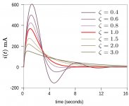
Not thanks, don't have the time or interest. But, I suspect where Small may have led you astray (and or himself) and what Scott may not want to get into with you has to do with the diagram below, or something rather similar.
There can be an optimal amount of (passive) damping (disregarding active methods for now), and to have a better idea of what it would have to be for typical loudspeakers I would have to spend time looking into speaker modeling. However, I gather the empirical evidence is that lower amplifier output impedance improves damping of ringing better than higher amplifier output impedance. That tells me enough.
Attachments
Last edited:
Modern speaker design assumes "high enough" damping factor. No conspiracy, no magic, no alternative facts.
High enough means it doesn't have to be considered. This is really 101 stuff.
High enough means it doesn't have to be considered. This is really 101 stuff.
10% from DCR of the driver itself is "high enough", lower output resistance of the amp does not matter. Better is only a negative output resistance, but it is a different story.
- Status
- Not open for further replies.
- Home
- Member Areas
- The Lounge
- John Curl's Blowtorch preamplifier part III