I haven't seen a lot of discussion of anode load bootstrapping. It seems like a fairly straight forward way of gaining advantages similar to active loading. Are there any significant drawbacks to using it?
Can something similar be done at the grid or cathode of a CC stage to increase input impedance? related to the input impedance question why is it that so few data sheets specify max Rg-k (interested in 12AY7 specifically)?
Can something similar be done at the grid or cathode of a CC stage to increase input impedance? related to the input impedance question why is it that so few data sheets specify max Rg-k (interested in 12AY7 specifically)?
mashaffer,
What circuit are you trying to build with the 12AY7?
How high of an input impedance do you need? Impedance at what frequency? Resistance?
You can bootstrap the grid resistor to the junction of two series resistors for a cathode follower.
The maximum grid resistance is dependent on self bias or fixed bias.
The input impedance of a 12AY7 due to miller capacitance of a common cathode stage that has gain near u, is much lower at 20kHz than the maximum grid resistance you can use.
I use a 50k Ohm volume control, with the wiper connected to the 1k Ohm grid stopper resistor. You could use more resistance in the volume control, but sooner or later you will loose high frequency bandwidth. The major input capacitance is ((1.7pF + (1.7pF times the gain) which is 1.7 + (1.7 x 40) = 1.7 x 41 = 68pF. You get that gain of 40, if you use a current source in the plate load, and an extremely large impedance at the next stage. (12AY7 u = 40). Capacitive reactance of 68pF at 20kHz = 117k Ohms. If the source impedance driving the grid is also 117k Ohms, you are -3dB at 20k Hz. A 234k volume control wiper at 1/2 resistance will have at least 117k Ohms, even if the input (top of the potentiometer) is shorted to ground (or source impedance as low as 0 Ohms).
I have used 12AY7 triodes in parallel for an input/driver stage (tone the capacitance). I used a 900V IXYS current source as the plate load (set to 7 mA, 3.5 mA for each triode). Each cathode had its own separate self bias resistor, and its own separate bypass cap. Separate self bias gave really good current balance of the 2 [parallel] triodes. I used separate 1k Ohm grid stoppers from the signal input. This configuration gave good gain, good linearity, and lots of output voltage swing to drive the single ended output stage.
I also used this same parallel triode 12AY7 circuit to drive a self inverting push pull output stage. The output stage push pull cathodes are tied together, and have a current source [actually sink] tied from the cathodes to ground (no bypass capacitor).
I have also used the 12AY7 in a long tailed phase invertor (transistor current source [sink]) with the cathodes tied together, and the current [sink] tied from the cathodes to a negative supply. You could also use an Integrated Circuit current source. There were separate resistors for the plate loads. Again, I used separate grid stopper resistors, one from the signal source to the grid, and another grid stopper resistor from the other grid to ground.
Remember, you get gain of less than 1/2 of u for long tailed phase splitters.
I am building some push pull amps again, and will quite likely use some 12AY7 tubes for the phase invertor/driver.
Last edited:
Looking at about 2Meg load for ceramic cartridge for simple consoles. I know 12AU7 and 6SN7 will do it but was curious as to what other triodes would be applicable. It seems that some 6N1P (Svetlana) spec out at only 500K. Good reminder that Miller might be a problem before instability becomes a problem.
Rather than leading with a gain stage using a CF buffer prior to a normal gain stage might indeed be preferable.
Rather than leading with a gain stage using a CF buffer prior to a normal gain stage might indeed be preferable.
Last edited:
Put a JFET source follower buffer inside the TT, right at the arm pillar's base. Part of the HF info. loss associated with piezoelectric carts. is the devices' high O/P impedance interacting with cable capacitance.
Heck, you might "get lucky" and need to partially implement the RIAA playback curve.
Heck, you might "get lucky" and need to partially implement the RIAA playback curve.
Thanks guys. My main question however remains the first. For Line Amps, Phono Stages, and VAS stages in PAs I wonder why a bootstrapped anode is so rarely seen. A fairly simple way to reduce distortion and increase gain. It seems like an especially nice way to get a 12AX7 in the zone.
P.S. would there be any advantage to combining it with local FB?
P.S. would there be any advantage to combining it with local FB?
A bootstrapped anode load is related to and works in roughly the same way as SRPP and mu-follower. For some reason the latter are popular (even where they add nothing) and the former is rarely seen. In some cases a bootstrapped load gives you more flexibility, because you are not constrained to having the same quiescent current in both valves.
If you have "large" plate resistor, significantly more than the datasheet rp, just use a huge grid resistor. 2Meg 5Meg 10Meg 22Meg.
The idle point will not be exactly as figured for small grid resistor. But with RP larger than nominal rp, it will be very self-correcting. If current gets high, not only does plate voltage droop, but more stray charge on grid tends to bias off, and vice versa. Not ideal for Large signal stages, usually fine for small signals like pickups.
The idle point will not be exactly as figured for small grid resistor. But with RP larger than nominal rp, it will be very self-correcting. If current gets high, not only does plate voltage droop, but more stray charge on grid tends to bias off, and vice versa. Not ideal for Large signal stages, usually fine for small signals like pickups.
Great discussion so far. A couple other points of discussion present themselves.
One is noise. Let's say for the sake of discussion that a follower is needed regardless of whether bootstrap is used or not. Does the bootstrapping affect noise at all? My assumption is that as long as the total physical anode resistors are of the same value the noise should remain the same even though the effective ac impedance is increased. If this is the case then in theory one could use the technique to either get higher gain at the same noise level or lower noise at the same gain level (by using smaller resistors) or something in between. Any truth to that.?
If a follower is not needed apart from the bootstrapping then of course the noise of the extra active device needs to be considered.
Another application that comes to mind is low B+ circuits where anode load is restricted by available B+. A bootstrap (possibly even using a jfet) could be of use.
> Does the bootstrapping affect noise at all?
We are talking about different things than your original issue.
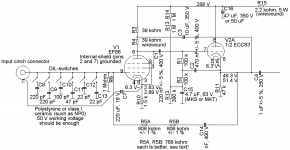
The plan in #8 bootstraps the gain stage, *and* uses NFB to replace a physical 47K resistor (needed for pickup damping) with a higher value (lower hiss current) 1,600K.
For your question of not-loading a ceramic cartridge, my answer holds. Use any value gridleak with a large plate resistor. Such data are shown on some datasheets.
GE data for 12AX7 shows 10Meg gridleak with 240+K plate resistor. Compared to low Rg with cathode bias, gain is a bit higher, max output a bit lower, no great difference.
We are talking about different things than your original issue.
The plan in #8 bootstraps the gain stage, *and* uses NFB to replace a physical 47K resistor (needed for pickup damping) with a higher value (lower hiss current) 1,600K.
For your question of not-loading a ceramic cartridge, my answer holds. Use any value gridleak with a large plate resistor. Such data are shown on some datasheets.
GE data for 12AX7 shows 10Meg gridleak with 240+K plate resistor. Compared to low Rg with cathode bias, gain is a bit higher, max output a bit lower, no great difference.
We are talking about different things than your original issue. <snip>
Yes, by putting to much in one post I am afraid I confused things a bit. The noise question is not related to the ceramic cartridge question but rather to a normal CC stage with a bootstrapped anode load as you might use in a line amp or magnetic phono pre, not a high Z input.
Do you mean a circuit similar to post #8, but without R5A, R5B and C14? If so, with or without cathode decoupling? If not, could you sketch what circuit you mean?
For the circuit of post #8, the impact of the bootstrapping on noise will be quite small as long as R4 is much greater than 1/gm.
For the circuit of post #8, the impact of the bootstrapping on noise will be quite small as long as R4 is much greater than 1/gm.

Another option for ceramic cartridges, if you *must* use them, is a fairly low value load resistor, maybe 3 - 5 KOhm, and a modern RIAA phono stage. The capacitive source impedance of the amplitude sensitive cartridge differentiates signal voltage into a small resistor just like a velocity sensitive magnetic cartridge into a large one.
All good fortune,
Chris
All good fortune,
Chris
So my next step is to run some sims with a dirty power supply to see how it affects PSRR. I am strongly considering building the circuit I posted above for my main MM table. I have most of the bits on hand and even have some 6N1Ps for followers. I also have a choke from a Hammond L-100 amp which I think has L in the mid teens.
As shown it favors noise over microphonics but I could make the AY7 first for the opposite effect.
As shown it favors noise over microphonics but I could make the AY7 first for the opposite effect.
Coming back to noise: an often-made mistake is to bias a triode at as high a current as possible in order to minimize noise. This minimizes white noise, but maximizes 1/f noise: there is actually an optimum where the total noise is minimal, and this also depends on any weightings used (RIAA-weighting, A-weighting, ITU-R 468 weighting). Merlin Blencowe (Merlinb on this forum) wrote a very interesting article about modeling noise in triodes.
- Status
- This old topic is closed. If you want to reopen this topic, contact a moderator using the "Report Post" button.
- Home
- Amplifiers
- Tubes / Valves
- Bootstrapping