I am almost finished an Aleph 5. It was from a kit but there was no mention of the mosfets having been matched by the vendor, and no documentation of any sort which could have advised me to match them myself (if it was even possible without more to choose from than the 12 supplied)
So does a mismatch explain the following?
Left channel. Idles at 1.65a at +- 34v, speaker terminal -130mv, one mosfet runs at 80C and the rest about 55.
Right channel. Idles at 2.6a at +- 34v, speaker terminal 300mv, one mosfet (actually in the same position as the hottest on on the left channel) runs at 90C and the rest at 70.
What should the current be approx, and the output offset?
Is there a more recent alternative for the IRFP244?
Thanks.
PS. This is my first mosfet amp, and first single ended amp. I gave up on the JLH high power version as it wasn't upto driving my hybrid electrostatic speakers (ML Aeons). The heatsink is massive (cost £100) and is fitted with a 100mm fan so I am not skimping on the build (I hope).
Last edited:
runs at 90C and the rest at 70.
That's dangerously high. Pull the mosfets and test the Vgs.
See "Matching Devices" on this page. PassDiy
Should test mosfets using 34v supply and with the current the mosfets will be using.
For example, the overall current draw may be 1.5A by a bank of mosfets, but each mosfets might see .25A.
Depends on the design.
Output offset should be as close to zero as possible. Are the input mosfets matched as well? You'll have to check them.
The IRFs all been around for a while.
Can use several different versions of the IRF devices, such as the IRFP240.
There are Fairchild alternatives as well. Infinieon are newer, but be careful of pin assignments.
IRFP244PBF Vishay / Siliconix | Mouser
IRFP240PBF Vishay / Siliconix | Mouser
Through Hole 1 Channel N-Channel Enhancement MOSFET | Mouser
Last edited:
find schematic adequate for your actual pcbs
then we need to advise what to do to be able of setting Iq and offset
in a meantime , find a way to get matched mosfets , that's crucial
you need matched ones for upper group , and matched ones for lower group , no need matching upper with lower ones
then we need to advise what to do to be able of setting Iq and offset
in a meantime , find a way to get matched mosfets , that's crucial
you need matched ones for upper group , and matched ones for lower group , no need matching upper with lower ones
That's dangerously high. Pull the mosfets and test the Vgs.
See "Matching Devices" on this page. PassDiy
Should test mosfets using 34v supply and with the current the mosfets will be using.
The IRFs all been around for a while.
Can used several different versions of the IRF devices, such as the IRFP240.
There are Fairchild alternatives as well. Infinieon are newer, but be careful of pin assignments.
IRFP244PBF Vishay / Siliconix | Mouser
IRFP240PBF Vishay / Siliconix | Mouser
Through Hole 1 Channel N-Channel Enhancement MOSFET | Mouser
Thanks, I'll do that.
Has anyone used the Exicon audio mosfets:
ECX10N20 which have a low S of 2 compared to over 5 for the IRFP244.
find schematic adequate for your actual pcbs
then we need to advise what to do to be able of setting Iq and offset
in a meantime , find a way to get matched mosfets , that's crucial
you need matched ones for upper group , and matched ones for lower group , no need matching upper with lower ones
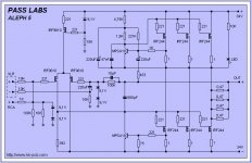
Here is the schematic which seems to have been used for the pcbs. (same component values).
I'll have to unsolder the mosfets and measure them at the design current (which is?)
Attachments
ECX10N20 which have a low S of 2 compared to over 5 for the IRFP244.
Don't know if laterals are right for the Aleph 5. Current rating usually lower on laterals, but there might other reasons, like low seimens.
around 0.5V across each source resistor
to set Iq , put trimpot in place of 220K in upper part of OS , say 100K resistor in series with 100K trimpot
to set DC offset , put 470R trimpot
both trimpots connected as variable resistor , wiper pin shorted to one outer pin
study this schematic for basic principles
to set Iq , put trimpot in place of 220K in upper part of OS , say 100K resistor in series with 100K trimpot
to set DC offset , put 470R trimpot
both trimpots connected as variable resistor , wiper pin shorted to one outer pin
study this schematic for basic principles
Attachments
around 0.5V across each source resistor
to set Iq , put trimpot in place of 220K in upper part of OS , say 100K resistor in series with 100K trimpot
to set DC offset , put 470R trimpot
both trimpots connected as variable resistor , wiper pin shorted to one outer pin
study this schematic for basic principles
Does the 470r go in series with R9 on your schematic?
Should I fit R8 as well?
Many thanks for your help.
470R trimpot instead of 392R (drain of input JFet) will cover entire range you need
no need for series resistor with trimpot
or you can put 270R resistor in series with 200R trimpot , to have finer setting
if you put trimpot there , no need for R8
no need for series resistor with trimpot
or you can put 270R resistor in series with 200R trimpot , to have finer setting
if you put trimpot there , no need for R8
470R trimpot instead of 392R (drain of input JFet) will cover entire range you need
no need for series resistor with trimpot
or you can put 270R resistor in series with 200R trimpot , to have finer setting
if you put trimpot there , no need for R8
Thank you.
I noticed that the mosfets were in 3 groups, 6 of the same number, 3 with a different number and 2+1. Of course I managed by chance to fit some in matching groups of 3, and the rest randomly chosen. I will check them all nonetheless.
while it's operational - measure voltage across each source resistor and write down by position
maybe , in fact likely - you'll have some matched triplets from them
then you need to buy less
maybe , in fact likely - you'll have some matched triplets from them
then you need to buy less
while it's operational - measure voltage across each source resistor and write down by position
maybe , in fact likely - you'll have some matched triplets from them
then you need to buy less
1 channel 0.6, 1.09, .88v and 1.22, 0, 1.36 total 2.6a, VGS 4.57
other channel 1.12, .34, .113 and .6, 044, .54 total 1.6 a VGS 4.22
So all over the place. What is an acceptable variation within a triplet?
I assume the variation in current is due to the IRF9610s also not being matched? But the 470R preset will take care of this or is it better to match the differential pair as well?
retype that , so I can grasp it .......
channel one , upper triplet:
channel one , lower triplet:
same for other channel
I don't care much of matching in input LTP ..... for now - you don't have where to check their currents
channel one , upper triplet:
channel one , lower triplet:
same for other channel
I don't care much of matching in input LTP ..... for now - you don't have where to check their currents
retype that , so I can grasp it .......
channel one , upper triplet:
channel one , lower triplet:
same for other channel
I don't care much of matching in input LTP ..... for now - you don't have where to check their currents
ch1
0.6V
1.09V
.88V
1.22
0 - DUD MOSFET
1.36
ch2
1.12
.34
.113
.6
.44
.54
oh boy ....... catastrophic
usual praxis is , at same current (500mA in case of Aleph 5) , measuring Ugs of mosfet
matched to 10mV
so - it's relatively easy now - either search to buy 4 matched triplets , or buy 3 dozens of mosfets and match them by your self ...... and you'll have some for later fun
usual praxis is , at same current (500mA in case of Aleph 5) , measuring Ugs of mosfet
matched to 10mV
so - it's relatively easy now - either search to buy 4 matched triplets , or buy 3 dozens of mosfets and match them by your self ...... and you'll have some for later fun
oh boy ....... catastrophic
usual praxis is , at same current (500mA in case of Aleph 5) , measuring Ugs of mosfet
matched to 10mV
so - it's relatively easy now - either search to buy 4 matched triplets , or buy 3 dozens of mosfets and match them by your self ...... and you'll have some for later fun
Yes, loads of fun matching a new batch. Should have bought the bare pcb not a kit of dubious unmatched parts but that's Ebay & I never learn!
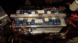
A5 WORKING AT 2ND ATTEMPT - mad build!
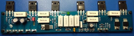
I rebuilt the A5 using a different pcb from a Polish seller and bought a batch of 25 IRFP244 so I could match them. (and also the IRD9610)
However I cannot be matching them correctly because one of them is running too hot with 0.4v across the source resistor compared to about .35v for the others.
I replaced the set of 3 with matched ones and strangely, the one in the same position is the hottest of the 3, still, at 80C.
I wonder if the 2mm ceramic insulators were a good idea?
I fitted a 3k3 resistor from g to s which has helped but is this a good idea?
I also had to replace the 220k resistor with a 100k preset which I put down to using lower gain BC546s instead of MPSA18s.
So at present the heatsink is running around 55C and that one mosfet is at 80C, with the rest at 60C. I may fit a cooling at at the bottom of the heatsink.
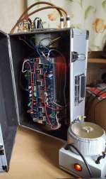
Yes, I built into a wheeled flight case with external psu with exposed toroid!
(the wheels are a good idea as it weights several Kg even without the transformer and there is absolutely no mains hum at all.)
Sounding good (compared to a Quad 405) but needs the gain increasing by about 6db as I do not have any preamp between dac and volume pot.
I rebuilt the A5 using a different pcb from a Polish seller and bought a batch of 25 IRFP244 so I could match them. (and also the IRD9610)
However I cannot be matching them correctly because one of them is running too hot with 0.4v across the source resistor compared to about .35v for the others.
I replaced the set of 3 with matched ones and strangely, the one in the same position is the hottest of the 3, still, at 80C.
I wonder if the 2mm ceramic insulators were a good idea?
I fitted a 3k3 resistor from g to s which has helped but is this a good idea?
I also had to replace the 220k resistor with a 100k preset which I put down to using lower gain BC546s instead of MPSA18s.
So at present the heatsink is running around 55C and that one mosfet is at 80C, with the rest at 60C. I may fit a cooling at at the bottom of the heatsink.
Yes, I built into a wheeled flight case with external psu with exposed toroid!
(the wheels are a good idea as it weights several Kg even without the transformer and there is absolutely no mains hum at all.)
Sounding good (compared to a Quad 405) but needs the gain increasing by about 6db as I do not have any preamp between dac and volume pot.
Attachments
Check for burrs around the attachment hole for the hot one. It might be keeping the ceramic insulator from making good contact. Did you use thermal grease on both sides of the insulators?
Oh, and post a picture of your MOSFET matching setup. We might be able to tell something from that....
Oh, and post a picture of your MOSFET matching setup. We might be able to tell something from that....
Check for burrs around the attachment hole for the hot one. It might be keeping the ceramic insulator from making good contact. Did you use thermal grease on both sides of the insulators?
Oh, and post a picture of your MOSFET matching setup. We might be able to tell something from that....
I didn't use heatsink grease and have some so will do that today.
I used a 40v 10a dual lab psu which also had a separate variable 6v output and tried two methods of matching.
A) 10r in the drain lead, G connected to D and increase the voltages until .5amp drain current was reached. All were within a few millivolts.
B) 10r in the drain lead, voltage set to 15 and then the gate volts increased until .5amp reached. All 25 were very close but I matched groups of 3 to within about 10mv. I only tested each one for 2-3 seconds i.e. before they heated up. (I didn't make a note of the readings)
I did check the heatsink for burrs but didn't inspect the mosfets or ceramic insulator for smoothness.
Thermal grease should lower the temps on all of them. It might even fix the "hot" one if the surface under it is rougher or has a slight dimple or something, but it's not a smoking gun like a burr would have been.
I doubt very much there's a burr on the ceramic (which has a honed finish) or the MOSFET (which has a ground finish).
Are you 100% sure there's no ridge around the "hot" hole? (Did you run a stone or diamond hone or something across it?)
On the MOSFET matching, how did you connect G to D? (Some of us were using patch wires and experiencing oscillation which threw the numbers off. They need to be connected right at the device.)
- Status
- Not open for further replies.
- Home
- Amplifiers
- Pass Labs
- Aleph 5 Query