No, was told by another Dutchman. 😉
Patrick
Ahh then it must be true of course; Dutchmen never lie.
When I say current or voltage feedback or abbreviate it as c.f or v.f., I am referring to to the Middlebrook Dual Insertion Test sense of this term. The article https://www.edn.com/design/analog/4458753/In-defense-of-the-current-feedback-amplifier is good reading and on page three under the section "Current Feedback or Voltage Feedback" you can find a good discussion of this technique. The type of the lesser of the two loop gains in a given circuit indicates the predominant type of feedback in that circuit.
My definition is that the signal current in a CFA's input stage flows through the feedback network, while that of a VFA does not.
I know and understand your definition. The problem is that you refer to an internal behaviour of the amplifier and not the way the feedback works.
The output current of the input stage is ~ the current which flows from the inverting input. OK.
But as the inverting input is the emitter and the output is the collector of the same transistor, you only say that ic ~ ie , which is not a revolution in electronics.
The name CFA suggest that the current feedback comes from the output and we know that it is not the case.
It is easy to see that this current is generated by the voltage between the two input of the amplifier.
So the real feedback mechanism of the so called CFA is the same as the VFA : it is voltage feedback.
And all that is done with so called CFA can be done with VFA.
The real difference between VFA and so called CFA is that the open loop behavior of the last one is partialy driven by the feedback network. That is not the case, or at least not at the same level in the VFA.
The name "Unbuffered VFA" given by Forr, is far better than "CFA".
But as the inverting input is the emitter and the output is the collector of the same transistor, you only say that ic ~ ie , which is not a revolution in electronics.
The name CFA suggest that the current feedback comes from the output and we know that it is not the case.
But where does the signal current in -in, that is the same as the input device output current, come from if not from the output?
It can only come in through Rf, there's no other connection. And the other side of Rf hangs off the output. So I don't see any physical path from the feedback current than from the output, through Rf.
Do you see another route?
Edit: I understand that Vb(e) influences the feedback current. Loosely, the feedback (error) current is Vout/(ol current gain) so the feedback current varies with Vout and thus with Vin. But don't confuse this 'control' with the origin of the feedback current!
Jan
Last edited:
At some point in this thread someone mentioned that a good criterium for calling a topology 'CFA' would be that the output current of the input pair is in fact the current into the inverting input. In contrast, in a VFA the output current of the input pair comes from the tail current.
Not sure how/why we lost that on the way but to me it seemed sensible at the time. Still does, in fact.
Jan
🙂 😎
WOW. yes, it does seem like there is a general agreement, finally.
Some where along this line we will have to also accept the IEEE usage... CMA and VMA.
Current-Mode and Voltage Mode Amplif. Unless that is different from CFB and VFB.
🙂
-RNM
Last edited:
But where does the signal current in -in, that is the same as the input device output current, come from if not from the output?
It can only come in through Rf, there's no other connection. And the other side of Rf hangs off the output. So I don't see any physical path from the feedback current than from the output, through Rf.
Do you see another route?
Jan
The feedback current, driven by (Vin+ - Vin-) voltage flows from transistor emitter, majority through Rg to ground and partially through Rf to output with respect to Ohm law.
The feedback current, driven by (Vin+ - Vin-) voltage flows from transistor emitter, majority through Rg to ground and partially through Rf to output with respect to Ohm law.
I agree, except to the 'majority to gnd, partially through Rf'. You can't say that as a generality, the fraction of the feedback current dividing to Rg and the emitter depends on implementation details.
Jan
When looking at VFA's and CFA's just as black boxes with a + and - input, (you call it the input pair) and an output, without knowing what's inside, the first part of your definition is perfectly clear.a good criterium for calling a topology 'CFA' would be that the output current of the input pair is in fact the current into the inverting input. In contrast, in a VFA the output current of the input pair comes from the tail current.
That’s the definition I proposed in 2014 - I put an article up on my website about it at the time as well.
But the second part is it a bit diffuse to my opinion.
That in a VFA the output current comes from the tail current demands knowledge of what's inside both boxes to be able to see this difference as a contrast.
And is it really true that a VFA always has a differential input pair fed by a tail current ? A buffered CFA, being a real VFA does not have this tail current, true ?
So isn't it enough to just say:
a good criterium for calling a topology 'CFA' would be that the output current of the input pair is in fact the current into the inverting input.
Hans
Here it is, coming fromA Christmas present : at last, I found thatsome time ago, you gave a very good definition for CFA
CFA Topology Audio Amplifiers
17th August 2013, 01:56 AM #188 Bonsai
I find it so good because it highlights the fact that sensing the voltage at the feedback divider node (which is not a voltage source, having a 100-500 Ohm typical impedance) is achieved by a current (coming from a low impedance voltage source, typical impedance 5-25 Ohm).Bonsai said:CFA for me means
The feedback is of the voltage sensing current type into a low z feedback summing node.
To avoid an alteration of the sensed voltage, only a very low value of sensing current msut flow into the divider node.
All electroncians know how to obtain such a tiny current. It needs another voltage very close to the one to measure. It's called the opposition method and was quoted by Cyril Mechkov in the discussion about CFA, link post #1.
Hans, I argued that an H bridge was in fact a CFA originally, but Scott pointed out that the semiconductor industry had defined it as a VFA. It’s behavior is that of a classic CFA - gain bandwidth independence high slew rates etc etc. I then recanted my view and accepted it as a VFA.
Then Prof Sergio Franco came along and said it was a CFA.
I’ll let Scott and the good Professor decide who is right on that one.
Point is, there is some overlap, and we can try to cover all bases, but we will not be able to, so let’s not waste time trying to. High loop gain CFA’s morph into VFA’s ( I am talking about power amplifiers here) because you have to deal with the OPS pole and associated phase shifts. That means, MIC, TPC, TMC or similar compensation design. However, the circuits still remain in essence what they are: CFA or VFA with fundamentally different operation of the front end.
You can build good amplifiers using either approach - just be aware of the pros and cons of each.
The article below was written to try to dispel some of the myths (ie b.s.) that were raging around CFA at the time (2014)
CFA vs. VFA: A Short Primer For the Uninitiated
Last edited:
Chris, please stop playing the victim game. You are not the subject of any campaign of ad hominem attacks, but only your understanding of feedback theory is under fire.
Please understand that by denying the evidence, shifting the targets, making unsubstantiated statements, challenging basic EE knowledge, denying you own statements made five posts up, making up quotes to defend the indefensible, etc... you are not helping the CFA cause (if anybody believes it needs to be defended, I don’t). I find that sad, but then it’s ultimately your own reputation on the line, not mine.
P.S. Check your facts. I left this forum over 8 years ago so I am new to this raging debate. There are enough people still around from then, to certify that I have no agenda or axe to grind against anything or anybody. Except Bybee devices, Shakti stones, green markers, magic pebbles, directional wires, and a few others, none of which apply here.
Syn08, I am still amazed by your unsubstantiated assertions ( the vague laundry list of your second paragraph), your outright erroneous claim of the gm fiasco, and posts which progressively focused more and more on me personally than on what I have written. And then on top of it, choosing to forgo substantial replies to my posts, you accuse me of acting to shut down the discussion! Finally, the evocation of a "Silent Majority" of folks reading this thread who knew how to separate the wheat from the chaff was, well, quite illuminating.
I am confident that an objective observer reading our conversation would express more concern over your reputation than mine.
I doubt that further exchanges between us would be any more constructive than the prior ones.
Hans, I argued that an H bridge was in fact a CFA originally, but Scott pointed out that the semiconductor industry had defined it as a VFA. It’s behavior is that of a classic CFA - gain bandwidth independence high slew rates etc etc. I then recanted my view and accepted it as a VFA.
Then Prof Sergio Franco came along and said it was a CFA.
Andrew, do H bridges indeed have gain bandwidth independence? Looking at the LM6171 data sheet I would say no, none is advertised, and I also don't think there is any theoretical reason why they should. Perhaps that's why the H Bridges like the LM6171 (for all purposes, an inverting input buffered CFA, see http://www.ti.com/lit/ds/symlink/lm6171.pdf page 16) are considered by Scott and others VFAs?
Can you point me where prof. Franco said H Bridges are CFAs?
Last edited:
I know and understand your definition. The problem is that you refer to an internal behaviour of the amplifier and not the way the feedback works.
The name CFA suggest that the current feedback comes from the output and we know that it is not the case.
That's precisely what is under under discussion, is it not?
It is easy to see that this current is generated by the voltage between the two input of the amplifier.
It is easy to see that I(in-) = I(Rg) - I(output through Rf) . Are you among those who say that there is no current feedback because the electrons flowing through the input stage do not flow through the output stage? If so, your claim leads to the conclusion that negative current feedback is impossible, as I have made clear in prior posts. Are you willing to state this? Please see the attached which better describes this point.
Secondly, Middlebrook's Double Injection Technique, nicely described starting at the heading "Current or Voltage Feedback?" on the third page of https://www.edn.com/design/analog/4458753/1/In-defense-of-the-current-feedback-amplifier , allows us to quantify the amount of voltage and current gains around the loop and to directly infer from that which form of feedback predominates in a given circuit. Guess which form generally predominates in CFAs? Are you willing to reject this technique?
By the way, as I said to forr a few posts back, it's not that voltage feedback doesn't exist in a CFA; it's just that there is typically more current than voltage feedback.
And all that is done with so called CFA can be done with VFA.
Even if I were to stipulate for the sake of argument that this is true, I fail to see the point that that would make.
The real difference between VFA and so called CFA is that the open loop behavior of the last one is partialy driven by the feedback network. That is not the case, or at least not at the same level in the VFA.
How would you interpret that claim in light of the fact that I can drive both CFA and VFA inputs with either current or voltage sources? Attached please find Middlebrook applied to a VFA to which a current source supplies feedback. Because of the use of the current source, Middlebrook demonstrates that c.f. predominates in this circuit, whose gain block is a VFA!
It turns out that if the impedance of the source seen by the feedback input exceeds that of the feedback input itself, c.f. predominates. Otherwise, v.f. does.
The name "Unbuffered VFA" given by Forr, is far better than "CFA".
If you are looking for a name that avoids describing the functional differences between a VFA and a CFA, that one works.
Let me thank you for keeping our disagreement on a technical rather than a personal level. It's a pleasure to exchange posts with you, especially after what I just went through.
Attachments

Andrew,Point is, there is some overlap, and we can try to cover all bases, but we will not be able to, so let’s not waste time trying to. High loop gain CFA’s morph into VFA’s ( I am talking about power amplifiers here) because you have to deal with the OPS pole and associated phase shifts. That means, MIC, TPC, TMC or similar compensation design. However, the circuits still remain in essence what they are: CFA or VFA with fundamentally different operation of the front end.
CFA vs. VFA: A Short Primer For the Uninitiated
Excellent article, thank you for sharing.
May I extract from your reaction that you want to keep the second part of your CFA definition as being important ?
And yes, there is probably no definition or test that doesn't have exceptions.
You have produced a very nice definition, where I have proposed a test that discriminates with a very high probability between the two.
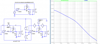
See #1837 showing different input currents and output voltages for different values of Rg when testing a CFA, where the VFA does not.
The H Bridge that does not fall into your CFA definition, comes out of my test also as a clear VFA, but again it's all a matter of definitions.
Hans
P.S. You are using loads of acronyms where I can only guess what they mean, but maybe everybody else knows their meaning. 😀
(TIS,TAS,TPC,TMC,OIC,OPS,MIC,ULGF,etc,etc.)
Last edited:
If you embrace the definition that a CFA is a CFA because the feedback current = input device output current, the H-bridge would not be a CFA.
Jan
Jan
If you embrace the definition that a CFA is a CFA because the feedback current = input device output current, the H-bridge would not be a CFA.
IMO, we don't really need to embrace any hard definitions to recognize the closed loop properties. That would save a lot of grief 😀.
But otherwise, since some naming convention is required to replace a half page description, then yes, an inverting input buffered CFA is in fact a VFA. A large closed loop gain morphs a CFA in a VFA (the small signal CFA magic properties are becoming vanishingly small, even the large signal properties (like the slew rate) are diminishing), etc...
The cores of the feedback mechanism are similar.CFA or VFA with fundamentally different operation of the front end.
The in(+) input transistor of a VFA does the job of
voltage sensing, current type, into the low impedance
emitter of the in(-) transistor acting as a follower of the
feedback voltage summing node
According to your definition,
the input transistor of a CFA does the job of
voltage sensing, current type, into the low impedance.
feedback voltage summing node
The cores of the feedback mechanism are similar.
The in(+) input transistor of a VFA does the job of
voltage sensing, current type, into the low impedance
emitter of the in(-) transistor acting as a follower of the
feedback voltage summing node
According to your definition,
the input transistor of a CFA does the job of
voltage sensing, current type, into the low impedance.
feedback voltage summing node
You may want to revise the above. The ideal non inverting input plays no role in the CFA feedback analysis, in fact this x1 buffer in the standard CFA model could be ignored safely in the first approximation. The role of the ideal x1 buffer is to provide a high impedance input, for practical reasons. In a second order approximation, the effect of the buffer non zero output impedance may be considered.
The complete process control of a CFA can be described as input stimulus "over-current" followed by "feedback current limiting”. This is to state that input stimulus precedes feedback taking place. It is upon this basis that there exists faulty reasoning existing in the document:
https://www.edn.com/design/analog/4458753/In-defense-of-the-current-feedback-amplifier
This begins on page 1 after Figure 3 (prior to Middlebrook). It states:
"Since the input buffer keeps Vn = 0, RG draws no current, so we must have In = (0 – Vf)/RF = –(1/RF)Vf, indicating that what comes back from Vf is only current and no voltage. It stands to reason to refer to this type of feedback as current feedback."
Figure 3 in the above website is reproduced as Figure 1. This can be converted to a Thevenin equivalent form of Figure 2 as to generate the same In currents. In Fig. 2 the input Vf is left to show how the value of V Thevenin is calculated as replaceable of Vf. Figure 3 transposes V Thevenin to the non-inverting terminal with R Thevenin connected to ground. The conclusion is that there is no difference between Figure 1 and Figure 3 in terms of behaviour of the inverting terminal.
This challenges the conclusion that "It stands to reason to refer to this type of feedback as current feedback." In the case of Figure 3 the output current is a function of V Thevenin / R Thevenin, the current being caused by a voltage being imposed on R Thevenin by V Thevenin. From this perspective this is voltage controlled current.
Without input stimulus in Figure 1 or Figure 2, feedback has nothing to respond to... hence a Vf signal can't exist in reality to render the conclusion of current feedback being true. This does not apply to Figure 3 for reasons that the CFA is responding to input stimulus voltage on R Thevenin connected to ground.
In conclusion a time delay exists between the input stimulus voltage causing stimulus current, being reduced in current magnitude by a changing and delayed V Thevenin rising to match the input voltage through a Thevenin equivalent resistance. The feedback process is of current, yet the action is of "current limiting"
Attachments
Then Prof Sergio Franco came along and said it was a CFA.
I’ll let Scott and the good Professor decide who is right on that one.
I missed that, given a fixed gm and dominant pole set by a C, I don't see there being any possiblity of constant BW with closed loop gain.
- Home
- Amplifiers
- Solid State
- Current Feedback Amplifiers, not only a semantic problem?