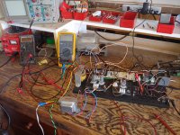
I've just breadboarded a basic schematic, as true to the original as I could find. But with only one gain stage, it's not very loud and, of course, there is no distortion. Was this Jim's intent? I would expect SOME breakup/clipping, to give the player that option. My transformers are not exact, voltages may be low, and I do have a large difference in the PI plate voltages (60VDC). My first thought is to put the two input stages in series, but then I would not have an original design. Any thoughts? Thanks in advance!
Attachments

Your schematic is a sawn off version of the original as the 18 had a tremolo input, much like the VOX AC series.
If you feed the amplifier with a couple of volts of signal, it will distort. Most guitars can deliver 2 volts of signal from the pickups.
Not a sought after design and short lived in the factory.
If you feed the amplifier with a couple of volts of signal, it will distort. Most guitars can deliver 2 volts of signal from the pickups.
Not a sought after design and short lived in the factory.
Thanks John! I'm basically wanting to play with EL84s in a P-P configuration. Do you have a favorite schematic that uses them? You prefer Cathode or Fixed bias? LTP or Cathodyne PI?
Something might be wrong with your PI section. Swap tubes, check your part values and connections.
EL84's are easily overdriven. One triode stage with a gain of around 60x and a PI with a gain of - say 10x plus - adds up to 600x plus.
60 volts low? Why? Post all your voltages. What kind of and quantity of speakers? I have a diy 18 watt with 2 12's and it is loud.
I've just breadboarded a basic schematic, as true to the original as I could find. But with only one gain stage, it's not very loud and, of course, there is no distortion. Was this Jim's intent? I would expect SOME breakup/clipping, to give the player that option. My transformers are not exact, voltages may be low, and I do have a large difference in the PI plate voltages (60VDC). My first thought is to put the two input stages in series, but then I would not have an original design. Any thoughts? Thanks in advance!
Not sure how you are testing them, but here´s a sample of the original one.
Not a high gain tone of course, but fine tasty late 60´s early 70´s distortion in spades.
Think Purple/Zeppelin , not Megadeath or Metallica 🙂
YouTube
There are various modded version Marshall 18w out there. BYOC makes a very good sounding kit version, and the schematic is freely available. You need good transformers to get the best sound though.
http://byocelectronics.com/tmb18schematic.pdf
TMB18 Amp Kit – Build Your Own Clone
http://byocelectronics.com/tmb18schematic.pdf
TMB18 Amp Kit – Build Your Own Clone
Printer 2 - Yes it was my PI, loose cathode lead. The amp ROCKS. Can't believe how little preamp gain (about 57) it needs! And the distortion seems to be coming from the power tubes. Need to hook my scope onto them to see the P-P, and 1 ohms on the plate leads to measure the power.... How do I adjust the bias (I'm used to fixed)....the cathode resistor? Thanks
> only one gain stage
This "PI" is a gain stage. About 25.
Figuring 50 in the 1st stage, 25 2nd stage, is gain of 1250 input to power grid. Figuring 15V will slam a EL84, we need 0.012V peak or 8mV RMS at the input. Input overload of 20mV is perfectly easy to rock with.
Cathode bias is also called "self bias". You do not have to fool with it.
What I have done in the past to mess around with the bias on a cathode bias amp is to put a higher value resistor in place and then parallel a smaller resistor across it to bring the combined ohm value down.
I am measuring 50mv across 1R on the EL34 plates, with 400 VDC on them. 400 less 14 VDC (cathode to gnd) x .05A = 19.3W per tube, 38.6W total, quiescent. Is this correct? Am I overpowering the power tubes? Cathode R is 120. Thanks!
I am measuring 50mv across 1R on the EL34 plates, with 400 VDC on them. 400 less 14 VDC (cathode to gnd) x .05A = 19.3W per tube, 38.6W total, quiescent. Is this correct? Am I overpowering the power tubes? Cathode R is 120. Thanks!
I just re-read what you wrote and you did deduct the cathode voltage. If I remember correctly I used a 180 ohm cathode resistor for that amp but the plate voltage was ~350. If I were you I would increase the cathode resistor to at least 150, but from memory I think 180 worked better. I would also try and lower the B+ to around 350.
Okay I am completely retarded.
This whole time I was thinking you were using EL84's because that's what the 18 watt Marshall uses but you said EL34 so I am confused. 19 watts is way too much for an EL84 but too low for a EL34. IF you are indeed using EL34's then you want something like 220R cathode resistor and you should be at around 28v on the cathode and close to 25 watts anode dissipation. I will have to look at an EL34 datasheet to get actual real numbers. What is the output transformer plate to plate load impedance?
This whole time I was thinking you were using EL84's because that's what the 18 watt Marshall uses but you said EL34 so I am confused. 19 watts is way too much for an EL84 but too low for a EL34. IF you are indeed using EL34's then you want something like 220R cathode resistor and you should be at around 28v on the cathode and close to 25 watts anode dissipation. I will have to look at an EL34 datasheet to get actual real numbers. What is the output transformer plate to plate load impedance?
MARSHALL 18W - OT impedance and plate current
I recently breadboarded a basic 18W amp (and posted recently about gain stages), but was getting way too much EL84 plate current. Plate voltage was a bit high (400VDC) but even lowering it (w/a Variac) to 365VDC, current was 59mA. So I changed the common 120R cathode resistor to 235R and voila, dropped to 40 mA. Much cooler... But why was the original value so wrong in my amp? Well, my OT was not spec'd exactly for the amp (6600R CT into 8R sec). But I just received a ClassicTone 40-18037 (correct for Marshall 18), and hooked it up. Wow - current dropped in half (from 40 - 20 mA)! It is spec'd with various primary R for different speaker windings (4, 8, 16R). My first OT had only 8R sec, and I had it connected to one 8R spkr. But I used the 4R sec on the new xfmr, wired to TWO 8R spkrs (in parallel of course). Documents said primary impedance would be 10.8K with 4R load). So, with everything ELSE equal except primary impedances, them being 6.6K then 10.8K should be the reason the plate current changed by about the same amount? Roughly doubling the primary impedance cut the plate current in half. Can I call the the reason? Just curious if my thinking s correct. Thanks!
I recently breadboarded a basic 18W amp (and posted recently about gain stages), but was getting way too much EL84 plate current. Plate voltage was a bit high (400VDC) but even lowering it (w/a Variac) to 365VDC, current was 59mA. So I changed the common 120R cathode resistor to 235R and voila, dropped to 40 mA. Much cooler... But why was the original value so wrong in my amp? Well, my OT was not spec'd exactly for the amp (6600R CT into 8R sec). But I just received a ClassicTone 40-18037 (correct for Marshall 18), and hooked it up. Wow - current dropped in half (from 40 - 20 mA)! It is spec'd with various primary R for different speaker windings (4, 8, 16R). My first OT had only 8R sec, and I had it connected to one 8R spkr. But I used the 4R sec on the new xfmr, wired to TWO 8R spkrs (in parallel of course). Documents said primary impedance would be 10.8K with 4R load). So, with everything ELSE equal except primary impedances, them being 6.6K then 10.8K should be the reason the plate current changed by about the same amount? Roughly doubling the primary impedance cut the plate current in half. Can I call the the reason? Just curious if my thinking s correct. Thanks!
Attachments
Those are AC impedance's and shouldn't effect quiescent plate current.
Things you didn't mention. What is the difference in DC resistance of the new vs old transformer? And what are the plate voltages between the two. My guess is the new 10.8k transformer has a much higher DC resistance and is dropping the plate voltage giving you less current.
Things you didn't mention. What is the difference in DC resistance of the new vs old transformer? And what are the plate voltages between the two. My guess is the new 10.8k transformer has a much higher DC resistance and is dropping the plate voltage giving you less current.
DC primary resistance of the first OT was 270R overall. Current OT is 620R. Yep, should have caused the change. Only I powered amp back up, and plate currents are now back where they were (after I lowered them to sane levels by doubling the cathode resistor from 120R to 235R). I have to slow down and go thru the changes I've been making - I'm trying to write them all down but it' still confusing. All in all, amp sounds good, I'm making changes and things are happening.... Been wanting to use the tube data sheet and draw a load line....have yet to figure that out!
Attachments
- Status
- Not open for further replies.
- Home
- Live Sound
- Instruments and Amps
- Marshall 18W - only one gain stage???