Good news!
Is there a specific interesting to know reason that you did choose for HF107 instead of HF10AK?
I jnow the two drivers znd the 10AK is superior sounding.
It is actually one of the smoothest sounding tweeters around.
Have you considered cutting the top cabinet edges above the woofer with a 1.5" radius quarter round router bit? You could also round the edges below the 15" woofer to maintain this style-point. On an 18" wide cabinet the STH100 and TD8M are small enough to allow this round-over. Earl Geddes SUMMA horn tweeter speaker cabinets all have large radius edge quarter rounds.
That's a great idea, the bits certainly aren't inexpensive, but that size of round-over should make a noticeable improvement in diffraction mitigation.
Cheers,
Gable
Hi LineSource, Gable
the rounded edge has been brought up before and it was on the first sketch for Tower XL, If I remember correctly Paul said that rounded baffle is not that necessary with this Mid and tweeter and directivity ( I may be wrong ) so we ditched it in next sketch 😀
Good news, crossing fingers here
Hey LORDSANSUI, thanks man 😀 same here.
Good news!
Is there a specific interesting to know reason that you did choose for HF107 instead of HF10AK?
Hey Paul 🙂
I waited some time for any comments on both mentioned models, there was no specific reason to go with HF107 except for the price difference, with my limited knowledge and by looking at the datasheets, I figured we can't go wrong with either 😀
I jnow the two drivers znd the 10AK is superior sounding.
It is actually one of the smoothest sounding tweeters around.
huh, saw this after I ordered, could use this before that, but both drivers are well known and I m sure we will not regret why we went with the other one 😉
huh, saw this after I ordered, could use this before that, but both drivers are well known and I m sure we will not regret why we went with the other one 😉
🙂😉
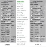
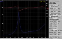
Some updates. I remeasured the TD8Ms, after some beating with 15 Vrms at 25Hz. The sensitivity is about 93 now with added mass method, DATS acting weird tho, I have to measure 10 times and each time it says that the mass is too small (49.5g) until finally it goes through, so at this point I don't trust it much, the QTS is also way too off, and it is the same with last measurement with TD15Xs, any ideas ? I will try to do some quick near field measurements tomorrow, I will also try to build a test baffle (not IEC tho).
The Re numbers measured by DATS is a little different with what measured by my Fluke 179, the calibrated resistor is 1000.7 (minus the leads), TD8M-1 is 6.3 (minus the lead resistance) and for TD8M-2 it is 6 ohms (minus the leads resistance).
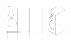
I did a quick and dirty drawing for the cabinet with new STH100 horn placement, I had to move the drivers around a little to make room for the horn.
I will start a shared folder for the Tower XL files, this way we can keep it clean and easily available.
Edit: I wanted to see if I can replace the HF107s with HF10AK but PS ran out of HF10AK anyways. So I guess the HF107 is a keeper 😀
The Re numbers measured by DATS is a little different with what measured by my Fluke 179, the calibrated resistor is 1000.7 (minus the leads), TD8M-1 is 6.3 (minus the lead resistance) and for TD8M-2 it is 6 ohms (minus the leads resistance).
I did a quick and dirty drawing for the cabinet with new STH100 horn placement, I had to move the drivers around a little to make room for the horn.
I will start a shared folder for the Tower XL files, this way we can keep it clean and easily available.
Edit: I wanted to see if I can replace the HF107s with HF10AK but PS ran out of HF10AK anyways. So I guess the HF107 is a keeper 😀
Attachments

Last edited:
DATS acting weird tho, I have to measure 10 times and each time it says that the mass is too small
I have no experience with DATS, but something might be wrong the with its TSP calculator. Do you get consistent impedance curves? Do you get the right result if you replace the driver by a resistor of know resistance (flat line instead of a peak)? If 2 x yes: please just measure the impedance curves with and without added mass and post the data files here. We should be able to work out the TSP from these data without DATS doing the calculations for us.
The room eq wizard is a freeware tool and it's able to measure TSP all well.
Aatto might give a try to compare with DATS.
REW - Room EQ Wizard Room Acoustics Software
Aatto might give a try to compare with DATS.
REW - Room EQ Wizard Room Acoustics Software
Aatto:
Like Matthias is mentioning also, please post the impedance measurements of TD8M with and without the added mass. From my side I will do an extra check in the Clio also.
I cannot believe the Mms should be about 15 g vs. 20 g in the datasheet.
If I do an impedance map in Leap on your impedance measurement, keeping Mms = 20 g, the sensitivity is 3 dB lower than in the datasheet. The dip around 1 kHz that is 92 dB in the datasheet will decrease to 88 dB, that is really on the limit. I am working at a first X-over to see if this can be a problem. More about it the coming days.
I did a quick and dirty drawing for the cabinet...
Hey that looks like a Monkey Coffin (for a big Monkey)! 😀
I will start a shared folder for the Tower XL files, this way we can keep it clean and easily available.
That's a good idea! Just make sure it's accessible for everyone around the world. I guess Google is not really an option in China, for example.
I have no experience with DATS, but something might be wrong the with its TSP calculator. Do you get consistent impedance curves? Do you get the right result if you replace the driver by a resistor of know resistance (flat line instead of a peak)? If 2 x yes: please just measure the impedance curves with and without added mass and post the data files here. We should be able to work out the TSP from these data without DATS doing the calculations for us.
I will try that.
The room eq wizard is a freeware tool and it's able to measure TSP all well.
Aatto might give a try to compare with DATS.
REW - Room EQ Wizard Room Acoustics Software
of course, I forgot about that, if I remember it uses soundcard input/out put as a closed loop to measure driver's impedance, I will give it a try.
Aatto:
Like Matthias is mentioning also, please post the impedance measurements of TD8M with and without the added mass. From my side I will do an extra check in the Clio also. I cannot believe the Mms should be about 15 g vs. 20 g in the datasheet. If I do an impedance map in Leap on your impedance measurement, keeping Mms = 20 g, the sensitivity is 3 dB lower than in the datasheet. The dip around 1 kHz that is 92 dB in the datasheet will decrease to 88 dB, that is really on the limit. I am working at a first X-over to see if this can be a problem. More about it the coming days.
Paul. I ll do what Matthias said, the numbers for QTs, Mms and sensitivity are way off, I don not think that AE would ever publish wrong or rigged numbers, it is a well known respected company, it might be the DATS but that's very unlikely since the hardware is simple enough, my guess is that the drivers are just held by my knees and not secured in a baffle as DATS and REW suggest to measure the parameters. about the baffle, I m in touch with Gable and we are planing to build a baffle and start measuring by next week or two, so that should be a lot of help, he has much more experience and space than me.
in the mean time I ll try to post the new measurements tonight.
Hey that looks like a Monkey Coffin (for a big Monkey)! 😀
That's a good idea! Just make sure it's accessible for everyone around the world. I guess Google is not really an option in China, for example.
it is a huge beast indeed, i m still haven't got over its size, haha.
as for the shared folder, it is available for public, anyone should be able to view the files freely. as for countries with no access to google, the files will be available here as well, I will try to update the first post more often.
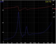
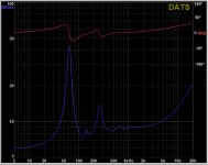
I had a little time with DATS this evening,
First I tried a regular 8 Ohm resistor and with resister I get flat response. Then I started with drivers, everything was calibrated again, I started with free air impedance measurement with drivers being held with my knees, what I found out is if I hold the driver tighter or looser it changes the curve and parameters.
I repeated the measurement for both TD8Ms a few times, with and without a 27.5g mass, without the mass the impedance curve is pretty consistent but with added mass it changes a little every time (vibration), and if I hold it tighter or looser it changes more.
Attachments


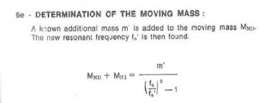
Using a simple formula (see attach) to calculate Mms with the added mass method, I find Mms = 19.95 g. That is almost perfect conform datasheet value of 20 g.
Calculated for driver 1 and taken fs = 98.7 Hz, fs' = 64 Hz and m' = 27.5 g.
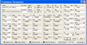
In attach the TSP of the driver model in Leap, fitting the impedance model on the last impedance measurement and taken Mms = 20 g.
You can see that BL of the driver is 10 N/A vs. 15.5 N/A in the datasheet.
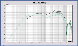
The SPL at 2.83 Vrms, 1m at 1 kHz is about 3.5 dB lower than the datasheet value and the SPL measurements on the AE website. The SPL dip at 1 kHz becomes 88 dB.
Edit: I added the expected SPL on infinite baffle at 2.83 Vrms, 1m of the TD 8M Aatto (green) vs. data of AE (black)
Calculated for driver 1 and taken fs = 98.7 Hz, fs' = 64 Hz and m' = 27.5 g.
In attach the TSP of the driver model in Leap, fitting the impedance model on the last impedance measurement and taken Mms = 20 g.
You can see that BL of the driver is 10 N/A vs. 15.5 N/A in the datasheet.
The SPL at 2.83 Vrms, 1m at 1 kHz is about 3.5 dB lower than the datasheet value and the SPL measurements on the AE website. The SPL dip at 1 kHz becomes 88 dB.
Edit: I added the expected SPL on infinite baffle at 2.83 Vrms, 1m of the TD 8M Aatto (green) vs. data of AE (black)
Attachments
Last edited:
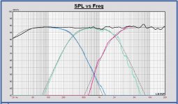
I did a X-over design with the current driver models, to check AE TD8M sensitivity and HF107 phase aligning with the midrange.
For TD15X and TD 8M I used driver models with impedance values of the last measurements and Mms of the datasheet.
For Faital Pro HF107 - STH100 I used the measurements of the Voice Coil test. I have eliminated the bafflestep response of their baffle in the test and added the bafflestep response of the Tower XL of an 8 inch driver at the tweeter position. All very roughly but useful for a X-over design check.
AC offsets: midrange at 0 position, woofer 30 mm backwards, tweeter 40 mm backwards.
Not used yet the last cabinet dimensions of Aatto's last drawings, the differences will be low.
It is an LR4 at 300 and 2000 Hz. In attach some results.
Some attention points and first remarks:
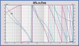
- Midrange sensitivity really at the limit at 1.1 kHz. Impedance dips to 6.06 Ohm. We have to carefully check this with own SPL absolute measurements.
- Sensitivity will we about 89 dB. It depends also on the F3 and F6 that is wanted. Now F3 = 36 Hz and F6 = 26.5 Hz
- Impedance at 20 Hz becomes 5 Ohm, I will look lower also later on.
- Impedance has high peaks, maybe it needs some compensation
- Phase aligning of tweeter and midrange is acceptable, better than I had expected. I have to look more in detail with the final responses. I have added groupdelay in attach, looks not bad around crossover frequency. An advantage of placing the tweeter a little backwards, it keeps the groupsdelay more flat above 1 kHz compared with an ideal LR4.
- LR4 is just an example design now. I prefer it, we will discuss later.
- Schematic not optimized yet, it is a first feasibility check now.
- No off axis yet, later on with cabinet measurements. I cannot make off axis models of the tweeter in Leap.
For the plots, woofer in blue, midrange in green, tweeter in red, sum in black, targets in grey.
For TD15X and TD 8M I used driver models with impedance values of the last measurements and Mms of the datasheet.
For Faital Pro HF107 - STH100 I used the measurements of the Voice Coil test. I have eliminated the bafflestep response of their baffle in the test and added the bafflestep response of the Tower XL of an 8 inch driver at the tweeter position. All very roughly but useful for a X-over design check.
AC offsets: midrange at 0 position, woofer 30 mm backwards, tweeter 40 mm backwards.
Not used yet the last cabinet dimensions of Aatto's last drawings, the differences will be low.
It is an LR4 at 300 and 2000 Hz. In attach some results.
Some attention points and first remarks:
- Midrange sensitivity really at the limit at 1.1 kHz. Impedance dips to 6.06 Ohm. We have to carefully check this with own SPL absolute measurements.
- Sensitivity will we about 89 dB. It depends also on the F3 and F6 that is wanted. Now F3 = 36 Hz and F6 = 26.5 Hz
- Impedance at 20 Hz becomes 5 Ohm, I will look lower also later on.
- Impedance has high peaks, maybe it needs some compensation
- Phase aligning of tweeter and midrange is acceptable, better than I had expected. I have to look more in detail with the final responses. I have added groupdelay in attach, looks not bad around crossover frequency. An advantage of placing the tweeter a little backwards, it keeps the groupsdelay more flat above 1 kHz compared with an ideal LR4.
- LR4 is just an example design now. I prefer it, we will discuss later.
- Schematic not optimized yet, it is a first feasibility check now.
- No off axis yet, later on with cabinet measurements. I cannot make off axis models of the tweeter in Leap.
For the plots, woofer in blue, midrange in green, tweeter in red, sum in black, targets in grey.
Attachments
-
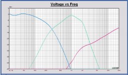 20181205 Tower XL AE version LR4 X-over electrical transfer.JPG131.4 KB · Views: 122
 -
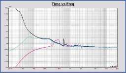 20181205 Tower XL AE version LR4 X-over Groupsdelay.JPG130.1 KB · Views: 123
 -
 20181205 Tower XL AE version LR4 X-over Phase.JPG154.7 KB · Views: 127
 -
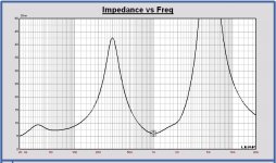 20181205 Tower XL AE version LR4 X-over Impedance.JPG114.2 KB · Views: 161
 -
 20181205 Tower XL AE version LR4 X-over SPL.JPG140 KB · Views: 453
 -
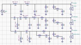 20181205 Tower XL AE version LR4 X-over schematic.JPG213.6 KB · Views: 455
Last edited:
Sorry if my last post looks chaotic and not easy to read, it was several posts that admins combined into one, didn't know that we pay by the post now !
@Paul: This is great, thanks for all your hardwork 🙂
we will have better measrements once we build a baffle with Gable.
@Paul: This is great, thanks for all your hardwork 🙂
we will have better measrements once we build a baffle with Gable.
I thought about other tweeter options for the Tower XL, also for the Faital version. Because the AC of the chosen CD tweeter Faital HF107-STH100 is 86 mm, there are other interesting concepts like AMT tweeters with horn with the same AC position. The X-over can be easily adapted. And there still is the dome tweeter with waveguide.
From my side I will fully support the X-over design for such tweeter options.
Some tweeters with horn/waveguide candidates are:
- Beyma TPL-150H; AC = 80 mm
- Mundorf AMT with horn. I did have some contacts via Banzai Music in Germany for more information about the Mundorf 88pp27R-14-462-H. They could tell me the AC of this driver is 77.5 mm. PDF of mechanical drawing of this driver with horn in attach. I did ask for off axis measurements also, but Mundorf didn’t have them available at this moment.
- Dome tweeter with waveguide equal as in the Monkey Box.
This post, just to tell that for those who prefer an AMT with horn or dome tweeter with waveguide, it is possble to make such optional design also.
And maybe more people get interest to build a Tower XL.
Attachments
Last edited:
hmm it's too quiet here, I wonder why.
Paul for the XO, I just wanted to know why you chose LR4 ? 🙂 any specific reason ? because of the delay issue with HF/mid alignment ?
Also, the 1.1k dip in TD8M concerns me, this is what some people had problem with with AE midranges, but I can see it's been compensated in XO.
I m hoping to have better results close to manufacturer with a test baffle.
do you think a test baffle would still be beneficiary or we can jump ahead to prototype baffle ?
also, do you think the difference in factory vs measurement numbers means the drivers may need more burn in time ? and regarding the burn in, since the amp get hot with TD8Ms i was doing it in short sessions and let it cool down in between, so it may effect the burn in process.
I am for high order X-over filtering, not typical for LR4. I have chosen now LR4, because it is very well known.
My personal favorite filter is elliptical, because it is even a steeper filter than LR4.
The reason I prefer high order filtering is to keep the overlap zone of the filtered drivers minimum for the best polar diagram. High order filtering also allows to design the filtered driver responses on standard targets down to more than -30, -40 dB of the nominal sensitivity for both amplitude and phase. In this way the time response of the filtered driver sum can be realized very close to that one of the chosen concept like LR, Buttterworth and others.
To improve the phase alignment with AC offsets, it is more easy to realize a better result with high order filters. Because more outband deviation off target can be allowed, because filtered SPL is lower at the same outband frequencies.
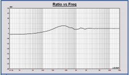
The 1.1 kHz dip of the AE TD8M is larger in the cabinet. Due to diffractions, the SPL becomes lower around 1 kHz and higher around 400 Hz w.r.t. the infinite baffle response. Look to the bafflestep response of the Toxer XL cabinet in attach.
Measuring the driver on a large IEC baffle will allow to reconstruct the infinite baffle response and compare the SPL with the one measured by the factory.
In general the IEC baffle measurement is interesting to analyze the driver response separated from the cabinet response and to compare parameters with datasheet values. Also to create infinite baffle driver models for simulation, the baffle is very useful. The IEC baffle is not needed to make a perfect speaker design if you are able to do good free space measurement outdoors or in an anechoic room of the drivers placed in the cabinet. As speaker designer the IEC baffle is very useful of course.
Burn in of the driver will not change the moving mass of the driver, only the compliance of the driver. As the SPL above fs is mass related, the dip at 1.1 kHz will not be changed by burn in.
I don’t think the short burn in sessions have a large effect on the measured parameters.
My personal favorite filter is elliptical, because it is even a steeper filter than LR4.
The reason I prefer high order filtering is to keep the overlap zone of the filtered drivers minimum for the best polar diagram. High order filtering also allows to design the filtered driver responses on standard targets down to more than -30, -40 dB of the nominal sensitivity for both amplitude and phase. In this way the time response of the filtered driver sum can be realized very close to that one of the chosen concept like LR, Buttterworth and others.
To improve the phase alignment with AC offsets, it is more easy to realize a better result with high order filters. Because more outband deviation off target can be allowed, because filtered SPL is lower at the same outband frequencies.
The 1.1 kHz dip of the AE TD8M is larger in the cabinet. Due to diffractions, the SPL becomes lower around 1 kHz and higher around 400 Hz w.r.t. the infinite baffle response. Look to the bafflestep response of the Toxer XL cabinet in attach.
Measuring the driver on a large IEC baffle will allow to reconstruct the infinite baffle response and compare the SPL with the one measured by the factory.
In general the IEC baffle measurement is interesting to analyze the driver response separated from the cabinet response and to compare parameters with datasheet values. Also to create infinite baffle driver models for simulation, the baffle is very useful. The IEC baffle is not needed to make a perfect speaker design if you are able to do good free space measurement outdoors or in an anechoic room of the drivers placed in the cabinet. As speaker designer the IEC baffle is very useful of course.
Burn in of the driver will not change the moving mass of the driver, only the compliance of the driver. As the SPL above fs is mass related, the dip at 1.1 kHz will not be changed by burn in.
I don’t think the short burn in sessions have a large effect on the measured parameters.
Attachments
Last edited:
Thanks Paul for the answer, I asked because of the endless battle between low order XO VS higher order XO, I do not yet totally understand how the phase shifts of higher order XOs can effect the sound, but I like the lower distortion of higher XO orders, IMO unless you design the drivers itself to match and work with other certain drivers or lucky enough to have very carfully selected and very well behaved and phycially aligned drivers, going with lower order XOs is maybe not the best choice or even an option.
I did have some experience with my miniDSP, for a while (couple of month) I have listened to my 10f/SBA FAST system with a S.Harsch xo, 4th order BR on Woofer and 2nd order Bessel on 10F with compensated delay since they were not AC aligned. after that I switched to a 2nd order XO with inverted phase on 10F and no time delay, and kept listening to it for a while, the 2nd order XO sounded more warm, so I understand why some prefer that but I didn't like it, to me the first setting with higher order LP has more snappy character, more detailed, and tighter bass, so that is what i have right now.
I will build the passive XO for the TXL since I like to have a passive system for testing amps but my main setup will run with miniDSP, that way i can play around and get more advantage of the system, one setup I would like to try is a 2nd order LP on woofer and 2nd order HP on tweeter with maybe 1st order bandpass on mid (B&O XO) this will need to have the delays compensated in XO which is not possible with a passive also the S.Harch XO, with 4th order LP and 2nd order Bessel band pass on mid and 2nd order Bessel HP for tweeter, with delay of 1/2 of WL of XO frequencies, this is also for AC aligned drivers but w calculated offsets delay for XO frequencies can be fun to tweak with.
Last edited:
hey Gable and thanks
That would be fun, I only have the 2x4 at the moment was waiting to see if they come up with new 2x8, but I will take you up on that, some experience with that will be fun 🙂
That would be fun, I only have the 2x4 at the moment was waiting to see if they come up with new 2x8, but I will take you up on that, some experience with that will be fun 🙂
Paul, et all:
I'm working on organizing for the driver measurements with Aatto, and I have some specific questions on a few points.
The IEC baffle will either be 175hz, or 200hz, with removable inserts for each driver and mount configuration.
Driver mounting and offsets (if applicable):
- Front Mount
- Rear Mount
- Flush Mount
For each driver, can you provide a list of which mounting(s) and offsets need to be tested? Making multiple inserts will be easy, so no issues making multiples if we want/need.
Software and Measurement 'config':
My plan is to make multiple sweeps (3?) of each driver/distance/axis.
So that begs the questions:
Is REW the right software to use? I'm familiar with taking measurements with REW, fwiw. I'm happy to use ARTA, or anything else that's open source/freeware, etc.
I have Mac and Linux laptops available. I have a UMIK for measurements, with calibration file.
What distance(s) do we need to measure? I presume 1m and maybe 3m?
Axis I have no idea about, I need to figure out an easy way to move the microphone position consistently. I don't think this will be difficult, especially if we only have a few specific angles for the measurements.
Voltage/Power, etc:
Is it ok for the measurements to all be normalized to a specific SPL, or a specific voltage, 2.83v rms, or whatever the 1w approximation is.
I'm sure I missed something above 😀
Cheers,
Gable
- Home
- Loudspeakers
- Multi-Way
- Open Source "Tower XL"