I didnt understand actually to which forum group it does it belong as does it comes to power supplies or amplifier forum because it generates sine wave power using an amplifier so i guess this is the right place to ask the question.
I saw the youtube video from paul from PS audio and found that the power regenerator is nothing but an amplifier with sine wave input with some variable. Please check the link given below.
YouTube
If i want a sine wave generation with out any PWM based sine wave generator can I use just an amplifier in either Class AB more or Class H mode in any one of it in bridge mode? basically how does this work as Im very curious about this power regenerator. Can any one explain how to do this with just using amplifier module? Considering 7 pairs of OPS transistor or may be 10 pair? What is the way to build a regenerator? Im guessing most of the loads are in less than 0.5ohms in the primary of the load. So does the amp be stable in that load as well? Some primary of the transformer in the load ( or equipment ) would it be consuming less current as primary resistance is higher? I would like to try the diy version of the power regenerator.
I didnt understand actually to which forum group it does it belong
The Lounge

THere's a thread over in "Analog Source" called "DIY 4 Phase Sinewave Generator for Turntable Motor Drive" that describes an AC power regenerator for a turntable. Many of the principles are the same. You might read some over there for some background info.
Exercise bike + induction motor.
It is a valid thing to want clean mains. Low voltage amp with a step-up transformer might be easiest and safest approach.
It is a valid thing to want clean mains. Low voltage amp with a step-up transformer might be easiest and safest approach.
Here is a working example, used as an integral of an instrument:If i want a sine wave generation with out any PWM based sine wave generator can I use just an amplifier in either Class AB more or Class H mode in any one of it in bridge mode? basically how does this work as Im very curious about this power regenerator. Can any one explain how to do this with just using amplifier module? Considering 7 pairs of OPS transistor or may be 10 pair? What is the way to build a regenerator? Im guessing most of the loads are in less than 0.5ohms in the primary of the load. So does the amp be stable in that load as well? Some primary of the transformer in the load ( or equipment ) would it be consuming less current as primary resistance is higher? I would like to try the diy version of the power regenerator.
Power-oriented cap-meter
It doesn't handle the full output power, it just correct a fraction, meaning the output power needs not be as large.
This one is dimensioned for 20VA, but using a bigger amp, it could be extended to any level
Exercise bike + induction motor.
It is a valid thing to want clean mains. Low voltage amp with a step-up transformer might be easiest and safest approach.
No a filter, the kind that all good amps have, is the easiest and safest. If your playing with high voltage and have limited knowledge, make sure your will is up to date.
I read PS Audio's patent on their regenerator a few years ago. From memory, it works this way:
First, they expect that the incoming AC waveform is not an ideal perfect sine wave with 0.0001% distortion. They expect that the job of the regenerator is to output a close-to-perfect sinewave with very low distortion, despite a possibly ugly load.
The cute trick is that the regenerator is an audio frequency (60 Hz) power amplifier that runs on just ±15V supplies. Although it delivers occasionally enormous currents, the power dissipated in its output stage is, at most, (Big_Current * 15V) which is manageable.
However the ±15V supplies ride on top of the incoming AC mains waveform. So the regenerator can only "correct" an amplitude error of about plus or minus ten volts. But apparently that's enough to get the job done in typical audio applications.
They generate a perfect sinewave and apply it to the "reference" terminal of their amplifier. This requires a phase locked loop, because the AC mains might be a few hundredths of a percent above or below 60 Hz yet you want the regenerator output to be the exact same frequency as the mains {atop which it rides!!}. Hence: PLL. As I recall, their PLL is implemented in software on a MC6800 family microcontroller.
The transformer is certainly not compulsory: it was already an active part of the design in my case, which is why I had no reason of forgoing it, but if none is needed, you could dispense with it.so is the transformer at the output is compulsory? Isnt it possible to make it without that?
I used a FB winding from the said transformer, but if no transformer is needed, a smaller one (1~2VA) could be used for FB if you don't want to alter the topology, but the best solution would be a redesign involving a direct potential divider from the output
https://www.audioxpress.com/assets/upload/files/simon2945.pdf
Any analog power amplifier that can put 1800 watts into an 8 ohm load will drive an AC power line directly. Used they can ocassionally be found for a few hundred dollars. Some improvement can be had by running your gear at a slightly higher frequency like 90 hertz.
Any analog power amplifier that can put 1800 watts into an 8 ohm load will drive an AC power line directly. Used they can ocassionally be found for a few hundred dollars. Some improvement can be had by running your gear at a slightly higher frequency like 90 hertz.
.....Im guessing most of the loads are in less than 0.5ohms in the primary of the load. ....
A half-Ohm at 120V is 240 AMPS. More than twice the current I can get at my house. Your guess is way-way off.
A 120V 120W load (a modest home high-fi) is 1 Amp, 120 Ohms.
The next innocent question is: what audio amplifier can make 120V swings (+/-168V peak)? Indeed some of the very large fixed-install amps are in this range. Or you can use a more modest-V high-A amplifier and a step-up transformer.
If this amplifier will supply ALL the power, then your 60Hz sine-source can be "just" an oscillator (which is a non-trivial thing if you need "perfect" power).
But the incoming line really has "small" defects. Mine will sag from 125V to 110V. If I can sync the local sine to the incoming "sine", then as Mark says you can put a +/-15V AC correction voltage in series with the incoming line. Watch for spikes/dips and dip/spike oppositely so the end result is 120V exact and smooth. This way only has to handle say 1/10th of the total load. The amplifier must be "nimble" to correct small errors, but we have that well worked out in Audio Amplifiers. The real problem is to get and hold good tracking and sift-out the errors for correction.
I have actually looked at such a thing to correct lamp-flicker when my well-pump cuts-in. Only as a mental puzzle: clearly it would be quicker to upgrade my pump or my power line. Possible but too crazy for my power flaws. And actually newer LED lamps don't dip-flicker as bad as incandescents or CFLs.
Power flaws: I have heard and seen the effect of 160VAC into a 115VAC amplifier. Flaws less than that, it is my opinion that the *amplifier* should suck it up and hide it from me. But I am not over-wealthy.
I read PS Audio's patent on their regenerator a few years ago. From memory, it works this way:
First, they expect that the incoming AC waveform is not an ideal perfect sine wave with 0.0001% distortion. They expect that the job of the regenerator is to output a close-to-perfect sinewave with very low distortion, despite a possibly ugly load.
The cute trick is that the regenerator is an audio frequency (60 Hz) power amplifier that runs on just ±15V supplies. Although it delivers occasionally enormous currents, the power dissipated in its output stage is, at most, (Big_Current * 15V) which is manageable.
However the ±15V supplies ride on top of the incoming AC mains waveform. So the regenerator can only "correct" an amplitude error of about plus or minus ten volts. But apparently that's enough to get the job done in typical audio applications.
They generate a perfect sinewave and apply it to the "reference" terminal of their amplifier. This requires a phase locked loop, because the AC mains might be a few hundredths of a percent above or below 60 Hz yet you want the regenerator output to be the exact same frequency as the mains {atop which it rides!!}. Hence: PLL. As I recall, their PLL is implemented in software on a MC6800 family microcontroller.
got it thank you very much.
Here is an interesting read! Mains Quality Among other things, Rod Elliott makes two observations. First that the very same dirty AC power that supplying the audio amp will ruin the sound is considered OK to supply the regenerator without affecting the amplified AC signal... The second is more interesting as he proves that the dirty AC results to better DC after rectification than the perfect sinusoidal AC!!!
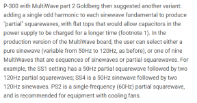
PS Audio, a company that sells AC power regenerators for audio equipment, agrees with Rod Elliott. They've even built a couple of these better-than-sinusoid waveforms into their regenerator. Collectively these alternative non-sine waveforms are called "Multiwave" ; perhaps because "Fourier" was already taken. Here's what the sales lit has to say, Figure 1 below.
edited a few minutes after posting: I found a review of the previous generation of PS Audio regenerator product, on Stereophile's website. It contains a discussion of Multiwave, and Rod Elliott would be very proud. Figure 2 below.
_
edited a few minutes after posting: I found a review of the previous generation of PS Audio regenerator product, on Stereophile's website. It contains a discussion of Multiwave, and Rod Elliott would be very proud. Figure 2 below.
_
Attachments

Last edited:
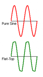
The main problem with "improved" waveforms is that they need to combine a number of (possibly conflicting) requirements: the peak value needs to be the same as for ordinary mains for usual peak-rectifying supplies, the rms value also needs to be identical, because of "historical" loads and servo/measurement systems based on it, the average value must be equal or preferably lower, to satisfy magnetics components like transformers and motors (traditional turntables for examples), it cannot depart too much from basic trig functions to allow motors to run reasonably smoothly and "roundly", and it cannot contain fast edges that may couple into unwanted paths.
If you build a single-purpose conditioner, you can pick and choose your waveform, but if you need to power a complete audio system with different components, this will narrow your choice, probably down to a single one if you want to be reasonably universal and compatible with various types and generations of equipments, and this single option is....
If you build a single-purpose conditioner, you can pick and choose your waveform, but if you need to power a complete audio system with different components, this will narrow your choice, probably down to a single one if you want to be reasonably universal and compatible with various types and generations of equipments, and this single option is....
There MUST be at least two waveform possibilities, and perhaps there are even more. The two which MUST be possible are the two that are deployed in the field right now, today, successfully powering audio equipment all around the world. Rod Elliott illustrates them in his article, Figure below.
_
_
Attachments
- Home
- Amplifiers
- Power Supplies
- Amplifier as Power generator example PS audio power plant