Hello to everybody, I am new in this forum and I need some help.
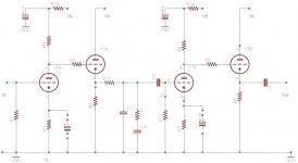
I diy a push-pull 30+30 watts on RCA schematic also including in the same enclosure tone control and RIAA pre-amp, immediately realise the mistake of include the RIAA in the same enclosure, sound great but lots of noise also, so decided to build a new phono pre-amp, I like this idea ( see schematic) but I really cannot figured out where to place the RIAA network and how to calculate the value of its components, I really appreciate some help.
I diy a push-pull 30+30 watts on RCA schematic also including in the same enclosure tone control and RIAA pre-amp, immediately realise the mistake of include the RIAA in the same enclosure, sound great but lots of noise also, so decided to build a new phono pre-amp, I like this idea ( see schematic) but I really cannot figured out where to place the RIAA network and how to calculate the value of its components, I really appreciate some help.
Attachments
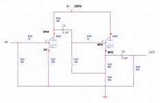

You can add the riaa network (totally passive) just after the CF, then you must have a similar circut for the output stage, one section with gain and one CF.
Bypass the cathode resistor with a cap for both gain sections
But with 6922 you will get not a very high amplification.
Maybe a ECC81 is better, with ECC83 you will get around 46 dB total.
Use a riaa network with a low impedance
R4,R5= 15 kohm 1%
C1=0,1 uF 5%
C2= 4700 pF 5%
R6,R7= 2200 ohm 1%
C3= 0,27 uF 5%
C4= 0,033 5%
Walter
Attachments
Hopefully you have some kind of resistance that loads the preamp in post #1.
Otherwise the 3.3uF and 1 Meg Ohm resistor will couple the DC voltage from the cathode follower for a very long time. 1 time constant is 3.3 seconds, and after 5 time constants (16.5 seconds) there will still be 5% of the cathode voltage across the 1 Meg Ohm resistor
(going to the next stage).
Otherwise the 3.3uF and 1 Meg Ohm resistor will couple the DC voltage from the cathode follower for a very long time. 1 time constant is 3.3 seconds, and after 5 time constants (16.5 seconds) there will still be 5% of the cathode voltage across the 1 Meg Ohm resistor
(going to the next stage).
Thank you to everyone for the massive help, now WALTUBE you mean that the RIAA network circuit has to be placed after C8 (3.3 uF), please confirm, yea I know about 6922 low amplification that's why I want to try it because this tube has also low noise, I already have a next stage that is a RCA tone stage here schematic, please let me know how can I properly couple the cathode follower stage to the tone stage. Thanks 6A3sUMMER so what do you suggest could be a proper cap?
Attachments
As has been pointed out, 1 6922 CC plus 1 6922 CF won't give you the gain you need. You can perhaps do 2 6922 CC plus 1 6922 CF stage.
I you have a good reason for wanting to use 6922, such as you already have them, you can build this one: RJM Audio - Tube passive phono preamplifier
Although the link is to an external site, designer is a member here and you can search for threads on this design.
I you have a good reason for wanting to use 6922, such as you already have them, you can build this one: RJM Audio - Tube passive phono preamplifier
Although the link is to an external site, designer is a member here and you can search for threads on this design.
You can add the network after the CF without any caps. At the end, before the gain stage you can add a 0,47-1uF cap to couple the stage
Is not reccommended to use the high value of R in series with riaa because the total noise will increase.
In addition with the coupling with CF and a low impedance riaa the loss at 1 Khz is around 1 dB and it is fine.
In the configuration I mentioned you can reach a very good s/n.
Of course a very good ripple attenuation is reccomanded
Walter
kissabout2002,
Consider how low of an impedance you will drive with the cathode follower; versus the output impedance of the cathode follower with the tube type and standing current of that stage (1/gm of that tube at that current). That cathode impedance is in parallel with its 10k cathode resistor when you are calculating the output impedance.
Now calculate what the cathode follower will drive. You want the load (next stage) to be 10X or more of the output impedance, or you will have gain loss, and any potential loss of frequency response because of the cable and next stages impedances at high and low frequencies). Or in other words, design the cathode follower to be 1/10 of the load impedance it will drive.
High frequency rolloff due to capacitive reactance (Cable's capacitance in parallel with the next stage's miller capacitance).
Low frequency rolloff due to the coupling cap capacitive reactance at low frequency, versus the parallel resistance of the 1Meg and the next stage grid resistor. capacitive reactance, Xc versus 1Meg in parallel with the next stage grid resistor. 1Meg and 111kOhms in parallel is 100k Ohms. Xc = 1/(2 * pi * f * C). solve for C, at the frequency you want, and Xc = Load Resistance Example: A 100k load and 0.32uF will be -3dB at 5 Hz, which is only -1 dB @ 10Hz. The RC time constant (R * C) is 100k * 0.32uF = 32milliseconds, 5 time constants is 160milliseconds.
The preamp needs to be considered as part of a system, including the next stage. The preamp is not a standalone device. Examples: Would you use an amplifier that only had a 16 Ohm output tap to drive a 4 Ohm speaker? Would you connect a 16 Ohm speaker to an amplifier's 4 Ohm tap, if it also has 8 and 16 Ohm taps?
I hope that helps.
Last edited:
One 6922 gain stage gives gain of 20 or 25, 26-28dB.
Phono preamps usually have gain at 1KHz of 50 to 100, 34dB to 40dB. At <50Hz they must have 10X more gain or 54dB-60dB.
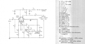
Two 6922 gain stages might do it with passive EQ. You could try it in the RCA circuit which is passive EQ.
However the "low noise" of 6922 may not apply in a phono preamp. We work phono preamps at fairly low current to reduce low-frequency hoise/rumble. Many-many very fine phono preamps have been built around 7025 (which is a low-noise 12AX7).
This is what RCA wanted you to do. If you still play records through tubes, this is still a fine plan.
Phono preamps usually have gain at 1KHz of 50 to 100, 34dB to 40dB. At <50Hz they must have 10X more gain or 54dB-60dB.
Two 6922 gain stages might do it with passive EQ. You could try it in the RCA circuit which is passive EQ.
However the "low noise" of 6922 may not apply in a phono preamp. We work phono preamps at fairly low current to reduce low-frequency hoise/rumble. Many-many very fine phono preamps have been built around 7025 (which is a low-noise 12AX7).
This is what RCA wanted you to do. If you still play records through tubes, this is still a fine plan.
Attachments
You can omit R12.
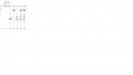
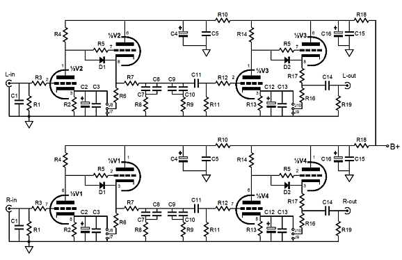
In attach the diagram of my phono built years ago. I found on my old folder!
So I send it that is crtified from some tests and I have published it on Audioreview magazine.
The riaa is the same
It works fine with ECC83 and ECC82 in origin; you can adapt easily for 6922 on CF.
The Vdc is about 220v.
list:
R2= 47 Kohm ½ w,
R1,R7= 1 Kohm ½ w,
R3,R6= 150 Kohm 1 w
R4,R9= 100 ohm ½ w
R5,R8= 12 Kohm 2w
R10,R14= 2K2 ohm 1 w
R11= 7K49 ohm ½ w ( you can use a parallel of 15 kohm)
R12= 1.090 ohm ½ w (you can use a parallel of 2.200 ohm)
R13 = 220 Kohm ½ w
R10,R14= 2K2 ohm 1 w
R15= 220 Kohm ½ w
C1= 0,1 uF 400Vdc polypropilene + 4700 pf in parallel
C2= 0,33 uF 250 Vdc polypropilene
C3= 4,7 uF 400 Vdc polypr.
C4= 0,27 uF + 0,033 uF in parallel 250Vdc polypr.
C5,C6= 47 uF / 350 Vdc
C7,C8= 100 uF 16 Vdc
without cathode bypass on gain stage you can reach 46 dB ( with 83), without you have around 40 dB without any changes on riaa response because the gain stage see a very high impedance from CF so the changing in the Zout of the 83 ( due the cathode resistor unbypassed) has no influence.
With the max gain, in this configuration the ratio s/n is little bit better than lower gain.
Walter
Attachments
That original RCA circuit may need some tweaks in the time constants... Looking at this schematic grinding through the numbers I get 3120uS instead of 3180uS for the 50Hz POLE.. I also get 67.5uS instead of 75uS for the 2.122kHz POLE... As for the ZERO @ 318uS ...I cant see it in the circuit...maybe I'm just tired...can someone help point out the ZERO circuit parameters..... Unless the ZERO is implied from the two POLE separation ??? I know some folks love the sound of this pre-amplifier.... These time constants can be easily dialed in more accurately if need be...
Last edited:
You need two of those stages for phono:I like this idea ( see schematic) but I really cannot figured out where to place the RIAA network and how to calculate the value of its components, I really appreciate some help.
Tetra Phono All-in-One & Broskie Impedance Multiplier
Good to know that Broskie has this diagram.
First building of my diagram was in 1994 then I made some little changes but still is a very good solution.
With a good stabilized power supply it is possible to get a high S/N and a reasonable overload capability on input
Walter
First building of my diagram was in 1994 then I made some little changes but still is a very good solution.
With a good stabilized power supply it is possible to get a high S/N and a reasonable overload capability on input
Walter
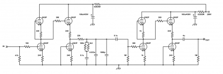
In this application? Basically fewer parts.use a DC coupled CF rather than the self-bias cathode follower, may I ask what is the difference?
Out of the one's I've build (about 4 now) this is the one I like the best. A lot like Walter's but with active loads. You can use a 6N1P, 12AU7, and others without circuit changes, and you can use 12AX7 (but why?) instead of 6N2P...
Attachments
Last edited:
Thanks to everybody I really appreciate the time you spend for reply to my questions and thanks for all the schematics given, now all is clear and I will do this project, thanks kodabmx I will for shure try your RIAA in the future, for now I have already the 6922 so I have to try with them, considering all I will go with waltube diagram but also very interesting is tetra phono all in one suggested by Merlinb, when the project will be finish I will post the result. Problem is I do not have oscilloscope and signal generator for the the measurement but I know is possible transform a laptop or pc with some software out there, if somebody of you knows let me know please, thanks again for all the help !!!
- Status
- This old topic is closed. If you want to reopen this topic, contact a moderator using the "Report Post" button.
- Home
- Amplifiers
- Tubes / Valves
- RIAA network on cathode follower