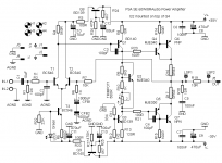
I wanted to squeeze last atoms of detail and resolution from Rod Elliott's popular circuit so I decided to make few changes to it. My circuit is in fact mixture of P3A and Motorola AN485 circuits. It uses CCS for the VAS transistor instead of Rod's bootstrap. Also, it implements suggestion from esteemed member Wahab for the front end noise filtering which consists of RC filter and capacitance multiplier. There are two compensation possibilities for the output stage, one from Doug Self's Load Invariant Amp which uses 100R base stoppers for drivers, or, alternatively, C4 fitted to Q5. I am not engineer so I have some questions:
1. My pcb will have two ground planes with separate faston connectors, one for the audio ground (feedback ground and input ground) and the other for the power ground. I connected RC filter ground, cap multiplier ground, and both CCS grounds to power ground. Is that OK?
2. Vbe multiplier is NPN. Is that OK because I've seen PNP used sometimes? Are the resistor values selected for the Vbe multiplier good for setting low bias in the range of 10-20mA?
Please report errors if you see them.
Attachments
Hello Ivan,
Nice one to try.
I have following suggestions which I have seen elsewhere and which may or may not be improvements.
1. a low value electro cap across C and E of VBE
2. 100R base stopper is too high?
3. gain is a bit low. purposely?
4. An electro (100uf) at the o/p of CMX before R3 and R23
5. Protection diodes for CMX across C-E
6. Protection diodes for o/p device for reactive speakers
I see you have become expert in eagle. well done.
Grounding is perfect. I used a similar CMX from Honey badger for one of the ESP amps in the i/p section. The gentleman who built it, reported improvement in SQ.
regards
Prasi
Won't the upper cap multiplier introduce noise into the VAS transitor Q1 base-emitter loop? A solution would be to include VAS stage into the same cap multiplier/stabilizer output. If the peak voltage from VAS is going to be an issue (not enough to drive the output into clipping) then higher supply voltage could be used for input+VAS.
Q8 is not needed, not a good idea, and shows incomplete understanding.
As drawn, it adds about a Volt between T1 and Q1. This forces an added 1V/10r= 100mA in Q1, which seems excessive.
Without the Q8 addin, T1 current in R4 reflects directly as voltage across Q1 and R8. Both these nodes are isolated from rail-crap by collector junctions. You want them moving together. Don't filter one and not the other; that just forces rail-crap onto R8 and into the heart of the amplifier.
Member
Joined 2009
Paid Member
Vbe cap will be added.Hello Ivan,
Nice one to try.
I have following suggestions which I have seen elsewhere and which may or may not be improvements.
1. a low value electro cap across C and E of VBE
2. 100R base stopper is too high?
3. gain is a bit low. purposely?
4. An electro (100uf) at the o/p of CMX before R3 and R23
5. Protection diodes for CMX across C-E
6. Protection diodes for o/p device for reactive speakers
I see you have become expert in eagle. well done.
Grounding is perfect. I used a similar CMX from Honey badger for one of the ESP amps in the i/p section. The gentleman who built it, reported improvement in SQ.
regards
Prasi
100R base stoppers can be lower.
Gain will be higher, it's just that I had to put some value on the schematic.
I think that I red sometime somewhere that output transistor catch diodes parasitic capacitance can introduce instability, but I will place footprints so that they can be added.
It's not problem to move cap multiplier to include Q1 and Q3.Won't the upper cap multiplier introduce noise into the VAS transitor Q1 base-emitter loop? A solution would be to include VAS stage into the same cap multiplier/stabilizer output. If the peak voltage from VAS is going to be an issue (not enough to drive the output into clipping) then higher supply voltage could be used for input+VAS.
Q8 is not needed, not a good idea, and shows incomplete understanding.
As drawn, it adds about a Volt between T1 and Q1. This forces an added 1V/10r= 100mA in Q1, which seems excessive.
Without the Q8 addin, T1 current in R4 reflects directly as voltage across Q1 and R8. Both these nodes are isolated from rail-crap by collector junctions. You want them moving together. Don't filter one and not the other; that just forces rail-crap onto R8 and into the heart of the amplifier.
Wahab gave suggestion for the P3A cap multipliers but did not defined what he meant as "front end", so I interpreted it as input stage. I will move cap multipliers to include Q1 and Q3.
The reason why I decided to upgrade P3A with additional noise filtering is that I observed sound quality improvement when I tried MrEvil's Cap Multiplier PSU with ESP P3A boards. I thought that adding cap mx to amp boards is way simpler and cheaper than using such elaborate PSU.I had a go at squeezing this design a few years ago, I think the P3a is a great amp.
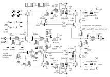
Corrected schematic attached!
The values of R11, R12 and R13 are directly copied from Motorola AN485 app note VAS transistor CCS. These values are for 36V supplies (60W/8R amp option). Now that we have some loss of negative rail voltage due to RC filter and cap mx interpolation, should these values be recalculated or is the loss so small to be insignificant?
The values of R11, R12 and R13 are directly copied from Motorola AN485 app note VAS transistor CCS. These values are for 36V supplies (60W/8R amp option). Now that we have some loss of negative rail voltage due to RC filter and cap mx interpolation, should these values be recalculated or is the loss so small to be insignificant?
Attachments
Last edited:
If you want to improve the P3A:
* Use a current mirror in the LTP stage
* Add emitter degeneration to the LTP stage
* Use MJE350 for the VAS, not BD140
* Add a VAS buffer
* Use MJE243/253 for the drivers
In other words... make it a Blameless amp. This defeats the point of the P3A design though, which was to produce a good sounding amplifier with minimal parts
Nicely corrected I think but you now have a problem with the effect on sound quality, despite the technically correct fix. What problem? Others could probably express this better but in simple (as in simple basic design) amplifiers such as the AKSA 55, NAP models, P3 etc. there is significant audio coupling between stages via the power rails which feeds back signal as well as PSU noise to the input stage, adding some likely pleasant sound effects as well as noise which is really the only part we should reduce. So by isolating stages with filters, we throw out the baby with the bathwater!
Nullifying the sound effects by isolating the stages of a proven, good sounding amp is usually counter-productive, depending on your aim of having technical or subjective improvement. Otherwise, we wouldn't waste our time on these simple, early designs but go for >20 transistors, state-of-the-art, ultra-low distortion laboratory amplifiers that engineers love to design and build.
Still, if you think you can improve sound quality this way, go ahead. More learning is good whether you listen to words of advice or to the music. Compare it directly with the original form and tell us what you think. I think you'll find Rod's design really is hard to beat for sound quality, whatever you try, as his comments and challenge suggest.
Hi Ian,
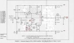
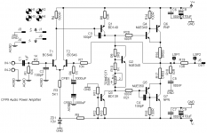
In fact I already have PCB design for AN485 which is even simpler (in it's original form) than P3A. I named the project CFP9. But there was a lot of free space on the board which had to have some dimensions because I wanted output coil on the board, so I wanted to fill that space with "improvements". But eventualy I may go for CFP9 which doesn't have noise filtering. See the attachements.
In fact I already have PCB design for AN485 which is even simpler (in it's original form) than P3A. I named the project CFP9. But there was a lot of free space on the board which had to have some dimensions because I wanted output coil on the board, so I wanted to fill that space with "improvements". But eventualy I may go for CFP9 which doesn't have noise filtering. See the attachements.
Attachments
Member
Joined 2009
Paid Member
The reason why I decided to upgrade P3A with additional noise filtering is that I observed sound quality improvement when I tried MrEvil's Cap Multiplier PSU with ESP P3A boards. I thought that adding cap mx to amp boards is way simpler and cheaper than using such elaborate PSU.
Will you build the original P3A in order to make a comparison so that you know if your improvements can be measured / heard ?
Any improvements are an opportunity to learn, which is the fun part of this hobby for me. Sometimes there are unintended consequences of making changes which adds to the story. You can put optional footprints on your pcb to try out different things.
...I named the project CFP9...
Looking at the schematic, some ideas you could consider - put a large bypass cap across ZD1 so shunt any 'zener diode noise' to ground. Include a 10R 1W 'ground lift' resistor into the signal input ground (I took this idea of Hugh Dean's AKSA design many years ago).
Often it is simply more satisfying to have a neat small-part-count layout to solder together.
the way i see it all these is more less pointless sorry to say
Choice of parts in such a simple circuit is a very critical thing and MJE 340-350 should be out of many audio devices MJe15030 also .
There is reasons why Rod is going for bootstrap rather than a CCS ask listeners most them will be able to tell you eventhough might not be able to tell you why
Then again adding things to circuit to make it better is one step after the one that one should make to see what can be done with existing circuit /choice of parts /mixmatching and so on
my 2 cents
I've seen that Doug Self designed Load Invariant amp with MJE340/350 drivers. Nobody said that his choice of drivers ruined the sound. Anyway, I use MJE footprints because it's available in the libraries and all TO126 devices have the same pinout so any suitable transistor can be used instead of MJE. I shall use MJE in test build because I have them in fully isolated packages so it will be much easier to put Vbe on top of one driver and to fix them both to small heatsink with one screw. My board will be specifically designed for that kind of Vbe mounting. See CFP9 board attached in previous post.
There is no ground lifter in my circuit because I never had hum/buzz problem in any of my builds without it. The only time I had serious hum problem was with VSSA and ground lifter did not solve it. Only Mr. Evil's cap multiplier solved it.
There is no ground lifter in my circuit because I never had hum/buzz problem in any of my builds without it. The only time I had serious hum problem was with VSSA and ground lifter did not solve it. Only Mr. Evil's cap multiplier solved it.
Looking at the schematic, some ideas you could consider - put a large bypass cap across ZD1 so shunt any 'zener diode noise' to ground.
Cap added to the CFP9 board!
- Status
- This old topic is closed. If you want to reopen this topic, contact a moderator using the "Report Post" button.
- Home
- Amplifiers
- Solid State
- P3A Special Edition question