If you want a metric for the effectiveness of a topology, divide feedback by THD. So say you have 80db/-100db. The metric is 180db. (my current amp in simulation has 260db at 20KHz, 130db/-130db).
If you want a metric for the simplicity of a topology, divide that by number of solder joints.
I wonder which amps would score the highest?
You could do the same thing with PSRR.
Maybe use no of P/N and N/P transitions in signal path so to cover for IC also...
//
http://www.diyaudio.com/forums/atta...ch-preamplifier-iii-input_noise_isolation-jpg
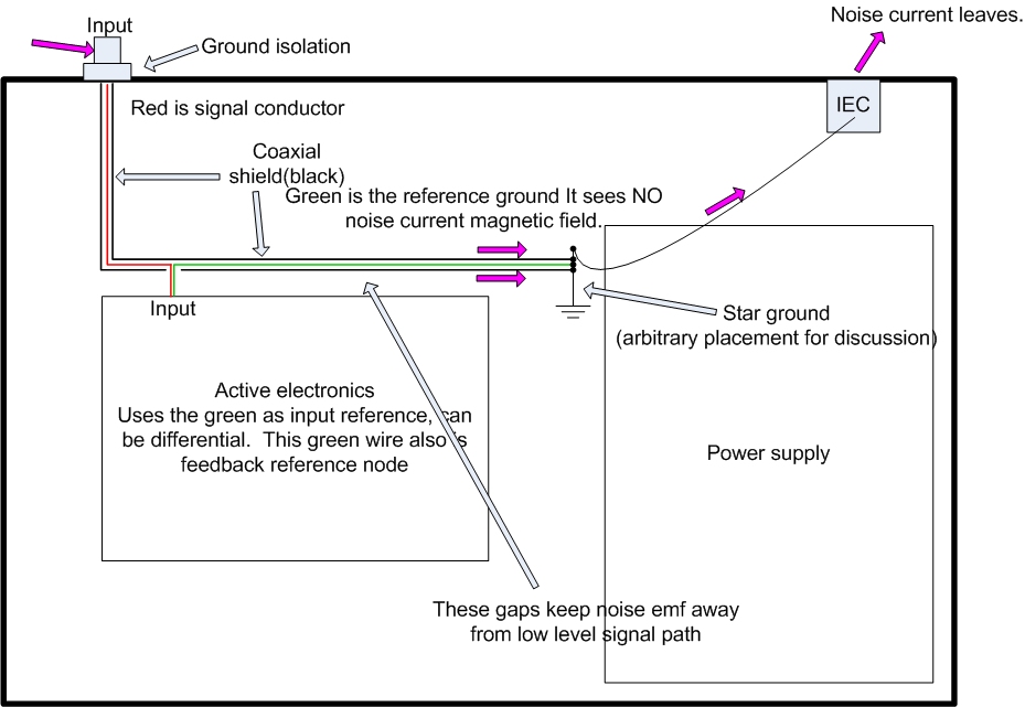
Recipe for disaster in my experience, and EMC giants like H.W.Ott would certainly agree. To work it needs the small signal part fully shielded because the whole inside of the outer chassis is polluted with radiated RF from the incoming cable shield. Relying on some distance as indicated in the drawing isn't enough with today's levels of GHz-ish RF.
Place the star ground at the RCA socket instead?
Good question, there are those that advocate measuring THD and not THD+N down to vanishingly low power. I have seen some surprising results published.
I said it was quite, too. .... THD at 2W/8 = .0001% and THD+N = .001% and at 1/8W THD = .0002% and THD+N = .005%.
As an example.
THx-RNMarsh
Last edited:
Richard, the question implied was far more about where the threshold of audibility is. (With the obvious caveats of situational dependency, test conditions, etc etc)
That's the key phrase. yes... If it is low enough. And, when it is not?
-RNM
Anything under 100ppm at 20kHz is already into total overkill for all bar dogs, monkeys and bats.
Did you miss the fact that the incoming cable shield isn't connected to the chassis except at the 'star point'?http://www.diyaudio.com/forums/atta...ch-preamplifier-iii-input_noise_isolation-jpg
Recipe for disaster in my experience, and EMC giants like H.W.Ott would certainly agree. To work it needs the small signal part fully shielded because the whole inside of the outer chassis is polluted with radiated RF from the incoming cable shield. Relying on some distance as indicated in the drawing isn't enough with today's levels of GHz-ish RF.
It challenges the world view, but I reckon worth investigating further.
That IS exactly the problem. A shielded cable going inside a chassis is a (unwanted) signal and needs its own shield to avoid emission.Did you miss the fact that the incoming cable shield isn't connected to the chassis except at the 'star point'?
Exactly. The "star GND" is on the inside of the chassis at the point where all the external connectors are located, that is, they should be crowded together (including mains inlet) and have all their backshells connected directly to the chassis.Place the star ground at the RCA socket instead?
That IS exactly the problem. A shielded cable going inside a chassis is a (unwanted) signal and needs its own shield to avoid emission.
The shield is grounded at both ends. As JN said
If the coax was terminating onto the PCB I would agree with you entirely. But it doesn't. It goes against what we have been taught to think, but I think is worth exploring, at least for those who haven't wussed out like me and Scott.I take advantage of the fact that a cylindrical shield has no internal magnetic field caused by the shield current. So, I kept the shield grounding connection to IEC chassis, but figured out how to prevent that current from getting into the signal.
Exactly. The "star GND" is on the inside of the chassis at the point where all the external connectors are located, that is, they should be crowded together (including mains inlet) and have all their backshells connected directly to the chassis.
Yes, I agree. Look at how benchmark does it. You'll see the RCA shells are tied to chassis directly I think.
Anything under 100ppm at 20kHz is already into total overkill for all bar dogs, monkeys and bats.
And this crowd YouTube
I see only one shield to chassis connection, and that is at the internal star GND. For RF the shield isn't well connected because of its inductance and that that's why this cable may re-radiate the current on it's shield into the enclose were it will echo around and creep into low-level circuits, causing demodulation. The audo signal is clean and well referenced, but the radiated emission from the incoming shield has been neglected. I'm shure a device built like this is prone to pick up the usual 218Hz TMDA noise from nearby cell phones. A bunch of ferrites would take care of that, or a shielding of the shielded cable to keep the RF outside of the enclosure. Of course, when the enclosure isn't a good shield because of larger openings etc RF will still enter...The shield is grounded at both ends. As JN said
If the coax was terminating onto the PCB I would agree with you entirely. But it doesn't. It goes against what we have been taught to think, but I think is worth exploring, at least for those who haven't wussed out like me and Scott.
The shield is conected at the RCA connector and then to the external cable and thence to wherever it came from. I think it warrants investigation as JN does tend to deal with larger H-fields than we have to cope with so thinks differently.
Rane say the screen of a balanced cable shouldn't enter the chassis for the same reason, so is it relevant that it's grounded both ends?
I did say it goes again perceived wisdom.
But JN does play in a different sandpit to the rest of us BNL Photon Sciences | About NSLS-II .
Is it a better way to do things? I don't know, but I'd like to work out how to test it.
But JN does play in a different sandpit to the rest of us BNL Photon Sciences | About NSLS-II .
Is it a better way to do things? I don't know, but I'd like to work out how to test it.
Look at it again.
There is text right next to the RCA saying "ground isolation". Maybe it should say "insulated from chassis".
There is text right next to the RCA saying "ground isolation". Maybe it should say "insulated from chassis".
Yeah, that is the main point of the image, the arbitrary placement of star ground which we should all discuss. Is it sufficiently arbitrary?
Sorry, I've been watching too many Monty Python clips on youtube.
I think a better text would be "arbitrary placement for brevity".
Sorry, I've been watching too many Monty Python clips on youtube.
I think a better text would be "arbitrary placement for brevity".
Last edited:
- Status
- Not open for further replies.
- Home
- Member Areas
- The Lounge
- John Curl's Blowtorch preamplifier part III