Sealed box volume, discrepancy in spec. v/s calcs.
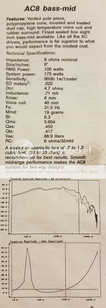
Being a beginner, I'm going to stick with a sealed box for this design. I found the spec sheet for the AC8 mid-bass that I'm using, which included this text "A sealed or aperiodic box of .7 to 1.2 cubic feet (20-35 liters) is required for best results".
However, when I employ the online calculators, using these data from the same spec sheet, they all seem to recommend a sealed box of 1.67 cubic feet (47.43liters).
What am I to make of the large discrepancy, and which to follow? I tend to think that the manufacturer would know best, what do you think?
Here's the spec sheet...
Last edited:
There is no discrepancy, it's simply that there are varying baseline assumptions. Your on-line software is probably assuming a Qtc of 0.7 with little or no leakage and no damping. A system Q of 0.7 (0.707 strictly) is maximally flat, i.e. has the lowest F3, which is not necessarily a good (or bad) thing. However, there are an infinite variety of possible alignments, albeit only a moderate range of practical ones.
Assuming the walls lagged & no leaks, 25 litres puts system Q around 0.82, give or take. 30 litres drops that to 0.77 or thereabouts. Converting those to aperiodic (leaky sealed) will drop the system Q relative to the box size -how much varies with implementation. What will suit you depends on exactly what you're trying to achieve, what the rest of the system & the room acoustics are like.
Assuming the walls lagged & no leaks, 25 litres puts system Q around 0.82, give or take. 30 litres drops that to 0.77 or thereabouts. Converting those to aperiodic (leaky sealed) will drop the system Q relative to the box size -how much varies with implementation. What will suit you depends on exactly what you're trying to achieve, what the rest of the system & the room acoustics are like.
Last edited:
For those, like me, with failing eysight: Vas = 3.14 cu ft; Qts = 0.417 and Fs = 31.5Hz.
Assuming a closed box Q of 0.7, a pencil and paper calculation gives a box volume of around 2.0 cu ft. This would give a resonant frequency in box of around 53Hz and a bass cut off frequency of around 40Hz.
But the main point is that it all depends on what system Q and bass cut off frequency you desire - put the driver in a smaller box and you get a higher system Q and raise both the resonant frequency and the bass cut off frequency.
Last edited:
P.S. If the driver is highly damped mechanically and electrically then it may be desirable to put it in a smaller box.
It may be overdamped if the box is too large and subsequently sound lacking in bass.
It may be overdamped if the box is too large and subsequently sound lacking in bass.
Can anyone comment on the damping of this particular driver from the specifications?
If it is highly damped then that will be why the manufacturer has recommended the smaller box.
If it is highly damped then that will be why the manufacturer has recommended the smaller box.
Last edited:
This unit is what most people would define a middling Q driver (aguably an effective Q of 0.707 is the fixed mid point with anything < 'low' and anything > 'high', but we rarely apply anything so rigidly) so EM damping is not especially large; a low Q driver is broadly considered to be < 0.3.
Without knowing anything else about the driver or its manufacturer, your guess is as likely to be correct as anyone else's, because that's all we'd be doing. Slightly higher Q alignments are sometimes liked for the extra bit of gain, at the price you'd expect. They do note aperiodic (not really, but we're never going to get the term changed) use also in those volumes, which as I noted will lower the effective system Q -how much depending on implementation. YMMV.
Without knowing anything else about the driver or its manufacturer, your guess is as likely to be correct as anyone else's, because that's all we'd be doing. Slightly higher Q alignments are sometimes liked for the extra bit of gain, at the price you'd expect. They do note aperiodic (not really, but we're never going to get the term changed) use also in those volumes, which as I noted will lower the effective system Q -how much depending on implementation. YMMV.
Last edited:
Thanks Scottmoose.
The use of an aperiodic box permits a smaller volume than would normally be indicated for a closed box. Its main effect is to lower the height of the bass impedance peak resulting in a clearer bass.
For the recommended 1.2 cu ft box, you would make a opening of area around 12 sq in at the rear of the box.
By squashing an inch or two's thickness of fibreglass into this hole and holding it in place inside and outside the box with some plastic mesh, you will form a resistive vent.
The inside walls of the box shold be lined with BAF wadding, being careful not to obstruct the path to the resistive vent.
Adjustment can be done by ear by adding or removing thicknesses of fibreglass until the bass response sound good to you.
I have successfully employed this method and ensure you that it is most effective, giving a more open sound than a completely closed box.
The use of an aperiodic box permits a smaller volume than would normally be indicated for a closed box.
Yes, that's what I said above.
Its main effect is to lower the height of the bass impedance peak
Just so, although if not done properly it can also introduce some variability around there (along with other factors), so some care is necessary in the design stages.
resulting in a clearer bass.
I'd agree to a contextual point; depends on what 'clearer bass' means. As I noted above it effectively lowers the box Q (slightly loose definition, but it broadly speaking has that effect) increasing the nominal damping, so if it's underdamped / suffering from excessive overhang the increased acoustic damping of the alignment can certainly help with that & subjectively should clean things up. However, it does come at a price; it will gradually shift toward a 3rd order acoustical rolloff & ultimately (albeit at a very low frequency & level so rarely an issue) unload 24db/octave. Done well these leaky sealed box variations can be very effective though.
For the recommended 1.2 cu ft box, you would make a opening of area around 12 sq in at the rear of the box. By squashing an inch or two's thickness of fibreglass into this hole and holding it in place inside and outside the box with some plastic mesh, you will form a resistive vent.
That's one way of doing it (Dynaco A25), though not the only one.
The inside walls of the box shold be lined with BAF wadding, being careful not to obstruct the path to the resistive vent.
Ditto. There are a number of implementations that use fiber-fill for instance, and in certain applications they do happen to obstruct the path. Depends on how it's designed & precisely what you're doing.
Last edited:
Thanks again Scottmoose.
I should have made it clear that my explanations and instructions were intended for WaxhawFive who states he is a beginner.
Just trying to keep it simple!
I should have made it clear that my explanations and instructions were intended for WaxhawFive who states he is a beginner.
Just trying to keep it simple!
Last edited:
OP, do you have winisd? It's all I use regularly so I can't comment on other software. It's free and will allow you to see the expected outcome as you change the box size. Likely with the big box you will get the flattest response that reaches lowest. As the box shrinks, the lowest notes reduce in volume, while the ones just above will increase. Taken to an extreme, you would loose the low end, and gain such a peak in volume on your new lowest note, that it would over-shadow all other notes. The one note wonder box found in a lot of car audio projects.
Perhaps that 35L box gives a little peak of just a db at 50hz before rolling off a bit quicker than the bigger box.
I'm just pulling these figures out my hat. There not specific to your driver. It's just how these things work.
winISD really is good. Giving the ideal sizes and plotting response curves. But also allowing you to adjust it's size afterwards, and watch how the graph moves. You can even have both boxes seen as different projects, and graphed out together. As winISD can open multiple projects at once.
@ Scottmoose
I find the topic of so-called 'aperiodic' loading interesting. You obviously know a lot about it. I have some information I would like to share with you. You may be aware of some or all of it, in which case I offer the information to WaxhawFive and other interested parties.
The source of the information is an article by Steve Hutton published by Hi-Fi News & Record Review in December 1974 which refers to the distributed port (DP) enclosure which was a type of aperiodic enclosure famously employed by Gilbert Briggs of Wharfedale fame. The DP consisted of a series of narrow slits or small holes in the rear of the enclosure which were covered internally by a thin, felt like cloth to form a resistive vent.
The article states that, as the DP area increases from zero, the Q and resonant frequency fall. However, after the Q has reached unity it starts to rise again with the figures becoming multi-valued, hence unpredictable, below Q = 1.
Most interestingly, the author gives an empirical formula for calculating the DP or resistive vent area:
A = 5.5 x V [0.818 (Fs/25) + 0.182]
Where A is the vent area in sq in, V is the enclosure volume in cu ft and Fs is the resonant frequency of the driver in free air.
The author goes on to state that the low frequency cut-off of a well designed DP enclosure is in the order of 1.5 to 2.0 x Fs, not as low as a reflex but better than a closed box of the same volume, while its transient behaviour is appreciably better than both, especially the reflex.
Hope the empirical formula may be of some use to the experimenters out there!
Last edited:
Bill Perkins at PEARL has probably done the most (and most advanced) work on aperiodic enclosures and his aperiodic implementation in the PEARL PR-1 is well worth paying attention to.
Buried in this document on the PR-1 development is more detailed information (Bill is verbose, the document is long):
https://www.pearl-hifi.com/03_Prod_Serv/PR2/Refs/PR_2_Expanded_Info.pdf
dave
Buried in this document on the PR-1 development is more detailed information (Bill is verbose, the document is long):
https://www.pearl-hifi.com/03_Prod_Serv/PR2/Refs/PR_2_Expanded_Info.pdf
dave
Thank you all for the comments and conversation. I just loaded WINISD, and created a new driver model for the AC8 using the data above. Playing with the box volume now. Plenty more questions to come...
OK, here's one now, is there a rule of thumb or formula to convert Mmd, to Mms? I did a little reading and it seems like Mms is sorta like Mmd plus the mass of the air it's pushing? Should those kind of questions be new topics so they're not buried in this thread?
OK, here's one now, is there a rule of thumb or formula to convert Mmd, to Mms? I did a little reading and it seems like Mms is sorta like Mmd plus the mass of the air it's pushing? Should those kind of questions be new topics so they're not buried in this thread?
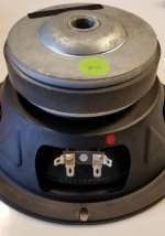
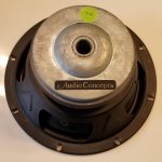
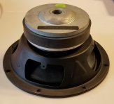
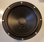
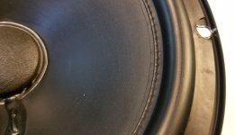
Here are a few photos of the driver in question. They were sold by Mike Dzurko's company, Audio Concepts Inc., a nice mail-order audio company out of LaCrosse, Wi. I bought them October 1992, they have since been played maybe 2 hours, and have been stored in an air conditioned space the last 26 years. I have no idea who the actual manufacturer was as there are no other markings other than the Audio Concepts decal.
Attachments
Last edited:
Looks like Eminence. I had their catalog - pretty cool stuff really. Thiel/Vandersteen type kits...I gonna go dig that out of the archive.
Last edited:
Looks like an ace driver. A large magnet with a ventilated pole and extended voice coil excursion. Is that a plastic cone? Stick 'em in the recommended enclosures and you should be cooking with gas!
OK, here's one now, is there a rule of thumb or formula to convert Mmd, to Mms? I did a little reading and it seems like Mms is sorta like Mmd plus the mass of the air it's pushing? Should those kind of questions be new topics so they're not buried in this thread?
Mms = Mmd + the air load m so to obtain Mmd you need to subtract the air load m which if memory and abominable mathematical ability serve correctly
m = [8/3]*ρ*r^3
Where
ρ = air density at a given altitude, temperature, humidity &
r = driver radius (from Sd).
I think I have a copy of the old HFN&RR article somewhere; I don't currently have time to look at it again in any detail, but the remark about transient behaviour being superior to a sealed box sans qualifications gives me a little pause, since a system Q of 0.5 is defined critically damped. The 1974 date suggests it may not have been fully exploiting Small's work by that point though.
Last edited:
Looks like an ace driver. A large magnet with a ventilated pole and extended voice coil excursion. Is that a plastic cone? Stick 'em in the recommended enclosures and you should be cooking with gas!
Well made drivers for the early 90's.
I had a couple of friends that were EE students in Dr Leach's class that used the AC12's.
So if I use the Hutton formula, I would get...
A = 5.5 x V [0.818 (Fs/25) + 0.182]
5.5x1(0.818(31.5/25)-0.182) = 4.5 sq in., that's about a 2 3/8" hole.
The ScanSpeak/Dynaudio vent is 12.5 sq in, so I figure it's too big per Hutton. I recall reading about some who will just drill a small hole on the rear panel and experiment by stuffing it with different densities of material.
So should I even bother? Should I just seal it up tight, or make the 2" opening, fashion a grill for both sides of the hole, and start experimenting with various densities of stuffing between the grills.
I guess what I'm wondering is will my ears even be able to tell the difference? Maybe I should try both and find out!? Maybe get my kids to participate in the experiment? Maybe their ears are still fresh?
Last edited:
- Home
- Loudspeakers
- Multi-Way
- Sealed Box volume, easy, right?? AC8