Hi X,
standby until thursday but I confirm that each BB board including two independant monitored FAN supplies (TC665 with FAULT output + to mosfet wired 100k NTC).
The I2C interface going to common (stereo) µC + OLED + 12VDC supply board (PCB part of main board but needs to be cutoff and placed on the front of the enclosure) who manages main power ON/OFF (would be nice to have a booster with shutdown capability? Thinking about LTC7812/13!).
I´ve to order 3D printed PCB mockup to check mechanical assembling (50€!).
JP
Wow, sounds good! I was thinking that just maybe I don't need this BigBoy-version, but not that sure anymore 😉
Hi,this is my first post on this very interesting thread, thanks to Mr.Hugh Dean, XRK971 and JPS64 for this project. As always questions:
Are boards for the 20W version still available?
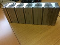
I have two banks of heatsinks as shown in the pictures, I do not know the CW of them, perhaps someone can assist and say if they will be suitable for one channel each ( 20W version )? They measure 400L x 150H x 90W.
Regards
Are boards for the 20W version still available?
I have two banks of heatsinks as shown in the pictures, I do not know the CW of them, perhaps someone can assist and say if they will be suitable for one channel each ( 20W version )? They measure 400L x 150H x 90W.
Regards
Yes, boards are still available. Add your name to the latest list.
I don’t see photos but the dimensions you give look very well suited for the 20W version. Probably could run 2amps bias even.
I don’t see photos but the dimensions you give look very well suited for the 20W version. Probably could run 2amps bias even.

Those are nice heatsinks. You would probably get better cooling if there was more separation between each of the sub banks of fins. Remove the half bank and redistribute the remaining. But it is so oversized you could use it as is.
Haha there is no adjustment to make if you did it right! The 0.33R source resistors “sets” the bias. The matched LTP transistors ensures low DC offset and tracking. If DC offset is off, adjust the pot R105. Connect voltmeter across R131 and fire her up. Voltage will take a second to appear and then will be about 0.61v (1.8amps across 0.33R or 1.3amp across 0.47R). Then check DC offset at output. Should be under 20mV and sometimes very close to 0mV if you set R105 at 1050ohm and matched the Hfe of the two KSA992’s. Use a light bulb tester if you have it but this amp is pretty straightforward it should be ok. Of course if voltage across R131 is > 1V for more than 2 seconds immediately turn off and debug.
There’s an AC modulation adjustment of Aleph CCS we can do later that requires putting AC signal and monitoring AC voltages across R131 vs R132 and adjusting pots R125 and R1270 to get the AC current in R132 to be twice the AC current in R131. (Read next to last paragraph of page 3 in Pass article on Aleph CCS).
If you used two 0.33R in parallel for R132, the adjustment is correct when AC voltages across R131 and R132 are equal.
http://www.firstwatt.com/pdf/art_zv2.pdf
Good luck!
Last edited:
Wow, no wonder there was no discussion about it, lol! An amp with low maintenance, even better.
I have matched the KSA992’s, installed .33R in R131 and .12R in R132 positions.
I should be good to go then.
Thanks for the fine print🙂
I have matched the KSA992’s, installed .33R in R131 and .12R in R132 positions.
I should be good to go then.
Thanks for the fine print🙂
This is probs very stupid question, but where pots should be set as a default? Fully clockwise, anti-clockwise or set on middle-position?
Set R105 to 1050ohms. The other pots R125 and R1270 are optional. If they are used skip the resistor corresponding. Set the pots nominal value to equal resistor it replaces (100k and 1k).
Last edited:
Hi XRK, PM sent.
Another question, I have two pairs of transformers available, which will be the best for the Alpha 20: 18-0-18 225Va or 24-0-24. 250Va .Each channel will have its own transformer. Is the Va rating enough for full 2 Amp bias?
Regards
Another question, I have two pairs of transformers available, which will be the best for the Alpha 20: 18-0-18 225Va or 24-0-24. 250Va .Each channel will have its own transformer. Is the Va rating enough for full 2 Amp bias?
Regards
Hello X,
I too am interested in a pair of boards if there are still some available.
Thanks!
Yes, please send me your PayPal address and I will send you invoice.
GB Status Update
34 pairs or 68 boards so far.
Pinocchio - 1 pair, Sent
6L6 - 1 pair, Sent
bk856er - 1 pair, Sent
Vunce - 2 pairs, Sent
Pcgab - 1 pair, Sent
jwjarch - 1 pair, Paid
vvs07 - 2 pairs, Paid
jacques antoine - 1 pair, Paid
GnuB - 1 pair, Paid
Kokanee - 2 pairs, Paid
zman01 - 1 pair, Paid
Bvtrinh - 1 pair, Paid
MshipmanPE - 1 pair, Paid
muthumuthiah - 1 pair, Paid
Schlomoff, 1 pair, paid
markus22ch - 1 pair, Paid
manniraj - 2 pair, Paid
Juntuin - 1 pair, Paid
Aatto - 1 pair, Paid
Wayne1 - 1 pair, Paid
Soelker - 1 pair, Paid
Touchdown - 1 pair, Paid
CFT - 1 pair, Paid
roger57 - 1 pair, Paid
Dane -1 pair, Paid
Gaborbela - 1 pair, Sent
wtl - 1 pair, Paid
Emynet - 1 pair, Paid
hajj - 1 pair, Please send PayPal address
alibear - 1 pair, Invoice sent
34 pairs or 68 boards so far.
I am fired up!! Mostly great news with a little bit of a puzzling situation.
Both amp boards are working and within spec for dc offset and bias voltage.
Board 1: 17.5mV offset, .604v bias
Board 2: 16.5mV offset, .603v bias
They are silent, no hum, hiss or any artifacts of any kind. Music sounds very good.
Now comes the puzzling part? When both boards are connected to the power supply, 2 seconds after the power switch is flipped both smps’s shut down.
If only one amp board is connected it works perfectly.
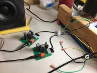
My power supply consists of:
(2) 24v smps->(2) dc voltage boosters->(2) cap Mx
The outputs of the cap Mx are wired in series to get +v/-v/0v before feeding the amp boards.
Any thoughts?
Both amp boards are working and within spec for dc offset and bias voltage.
Board 1: 17.5mV offset, .604v bias
Board 2: 16.5mV offset, .603v bias
They are silent, no hum, hiss or any artifacts of any kind. Music sounds very good.
Now comes the puzzling part? When both boards are connected to the power supply, 2 seconds after the power switch is flipped both smps’s shut down.
If only one amp board is connected it works perfectly.
My power supply consists of:
(2) 24v smps->(2) dc voltage boosters->(2) cap Mx
The outputs of the cap Mx are wired in series to get +v/-v/0v before feeding the amp boards.
Any thoughts?
Attachments

I suspect too much capacitance on the dual SMPS. This is a limitation of this type of power supply and they will often shut down if capacitively overloaded.
Take out the Cap Mx on both, and retest for the two amps. If both smps work fine, then you may have too much capacitance in the Mx. Then you may have a problem reducing the ripple with the missing Mx, and it might just be more viable to use a linear supply, using a 250VA toroid with two 18Vac secondaries and then a Cap Mx.
HD
Sorry forgot pictures in first post
those are very nice heatsinks indeed..any part number / availability on online?
Hi Hugh,
I use this same setup for my MoFo amplifier (albeit just single voltage) with far greater capacitance on the cap Mx output (44,000uF) without ever a problem. That’s why I was surprised they shut down in this application.
I used 16awg wire in the MoFo power supply, this setup has a small section of 24awg wire that exits the capMx. Do you think when both amp boards are connected this section of wire creates to much resistance at turn-on?
- Home
- Amplifiers
- Solid State
- Aksa Lender P-MOS Hybrid Aleph (ALPHA) Amplifier