Would anyone be interested in a layout designed specifically for a desktop version of this amp
This is exactly what i was waiting for, cheers!
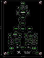
Here is the first draft 🙂.

Yep, the board is bigger than it needs to be (100 x 140mm), but it'll be easy to work with and traces are kept short. Ground plane for the power section and star ground for signal. Comments and crit are welcome.
Feel free to make requests. Coupling cap sizes are based on the tried-and-true components from the various pocket amp builds. But if someone wants bigger input caps or whatever we can open the discussion.
Edit: would folks like to see provision made for the inductor mentioned in post #1520? X, how big would a suitable air-core be?
Last edited:
I think some provision for film caps on input would be nice. As it is a desktop build we aren't inherently constrained to size, as in the PCA.
Maybe even just as a bypass cap for the input lytics?
Maybe even just as a bypass cap for the input lytics?
I like the layout quite a bit, power well away from low voltage signal, looks like a great format to make an awesome desktop amp.
BDHM,
Awesome layout! I agree that some room for fat boutique axial style poly film caps on input would be great. Maybe larger output bypass film caps would be nice to have. Provision for input RK09 volume pot (optional) would be nice. Those who don’t want it can solder jumper bridges. Power indicator LED after cap Mx at output of CRCRC.
For inductors maybe laminated steel core would’ve better for compactnes. These 20mH 0.5ohm DCR speaker crossover coils would probably work well. Let me run sims of these but in meantime, can you check to see if 2 can fit?
ERSE Super Q 20mH 16 AWG 500W Inductor Crossover Coil
BDHM,
Awesome layout! I agree that some room for fat boutique axial style poly film caps on input would be great. Maybe larger output bypass film caps would be nice to have. Provision for input RK09 volume pot (optional) would be nice. Those who don’t want it can solder jumper bridges. Power indicator LED after cap Mx at output of CRCRC.
For inductors maybe laminated steel core would’ve better for compactnes. These 20mH 0.5ohm DCR speaker crossover coils would probably work well. Let me run sims of these but in meantime, can you check to see if 2 can fit?
ERSE Super Q 20mH 16 AWG 500W Inductor Crossover Coil
Good points on the output caps and volume pot.
I've been looking around for the stencil design for the altoid tin pocket amp but either can't find it or it hasn't been posted. It seems to small for me to solder but I have only slightly more then zero experience soldering. I think the best option would be to get a stencil and use solder paste. Does anybody have any suggestions for how I can do this?
You don’t need a stencil for one amp. Just use solder paste applied with a syringe and hypodermic needle nozzle. Stencils are for production of multiple boards. Use a hot plate to reflow the solder after parts are placed.
I think some provision for film caps on input would be nice.
I'll be using just films on the input for my amp. In my mind a 2.2uF or 3.3uF polypropylene could be ideal...those have a wide lead spacing though.
Could you elaborate a little more on the hotplate thing? Do you mean like a hotplate that you would cook pancakes on? I already have the solder paste in a syringe.
Yes, a $10 hotplate cooker and a small nonstick aluminum skillet (don’t use for food again). Heat on medium and wait for paste to turn shiny liquid silver. Watch parts align via surface tension and make sure all have melted. Carefully remove plate and place on wet paper towel to quench and quickly remove heat to prevent excessive time components spend at high temps. An IR thermometer is useful if you have one but not necessary if you don’t let it cook too long.
https://www.walmart.com/ip/Elite-Cuisine-ESB-300X-Single-Burner-Hot-Plate/8467243
https://www.walmart.com/ip/Elite-Cuisine-ESB-300X-Single-Burner-Hot-Plate/8467243
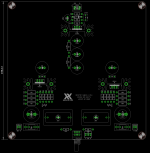
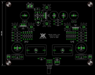
Bigger bypass caps, provision for chunky input film caps, and RK09 pot have been added 🙂. Input cap footprints are 27.5mm and 22.5mm lead spacing suitable for Wima, Kemet, or Panasonic, as well as many boutique caps.
Board is now 150mm square. I can get it down to around 100 by 130mm at the cost of less elegant traces.
I'm still working on the 20mH inductor. Those things are each 140 by 40mm 😱. Is a ferrite core inductor a no go?


Board is now 150mm square. I can get it down to around 100 by 130mm at the cost of less elegant traces.
I'm still working on the 20mH inductor. Those things are each 140 by 40mm 😱. Is a ferrite core inductor a no go?


Last edited:
Those layouts are looking great!
FWIW, I'm good with the 150x150 layout, it's a desktop build so for me that means having plenty of room to build an all out HA.
FWIW, I'm good with the 150x150 layout, it's a desktop build so for me that means having plenty of room to build an all out HA.
I’m looking into those ferrite toroidal 20mH inductors. They certainly are a lot smaller. We may be ok with 100mA dc current. Those big speaker steel laminated core Erse ones seem a bit out of place and expensive. I can get nice 100mH 10A microwave oven chokes for almost free but of course they weigh 10lbs! But they sound great on my MoFo.
Thanks for indulging our requests - the new layouts look great. I don’t mind a 150mm x 150mm square but I guess we should look into a convenient size and reasonably priced case to with it.
Thanks for indulging our requests - the new layouts look great. I don’t mind a 150mm x 150mm square but I guess we should look into a convenient size and reasonably priced case to with it.
I used 1.36uF on the input of my second mint tin build and the bass is awesome. (The weird value came from stacking two 0.68uF WIMA PPS caps in parallel.)
It will be great to have more room to play with on this desktop board 🙂
It will be great to have more room to play with on this desktop board 🙂
Last edited:
cool then, i have a pair of Cornell Dubilier 940c 1.5uf laying around, gonna give it a try. caps alone are almost as big as the board itself.
cool then, i have a pair of Cornell Dubilier 940c 1.5uf laying around, gonna give it a try. caps alone are almost as big as the board itself.
I see the lead diameter on those is 1.2mm. I'll add some bigger pads.
- Home
- Group Buys
- xrk971 Pocket Class A Headamp GB