Hello again, may I ask if voltage rating of input cap have any impact on the sound? Thank you.
Hello, allow me to share my journey with this chip. So
me of these pictures have been posted here during my troubleshooting days. Now all is well and it's playing music nicely. Pardon the double posting.
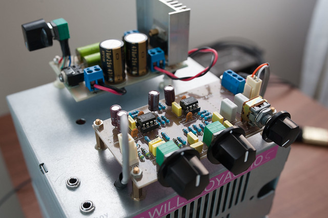
Here's how it arrived from eBay:
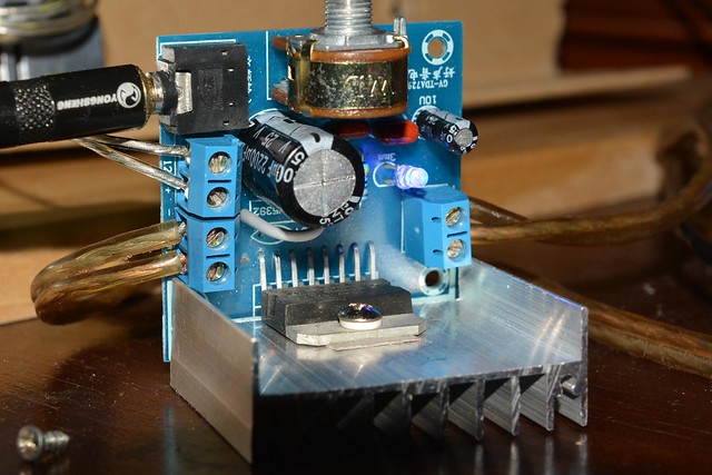
I learned that input cap value has an impact on frequency response, and that long leads are potentially bringing RF interference.
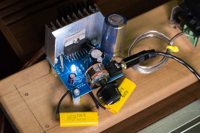
Together with a friend designed a PCB, after a long learning curve I realized that this can be much tighter layout.
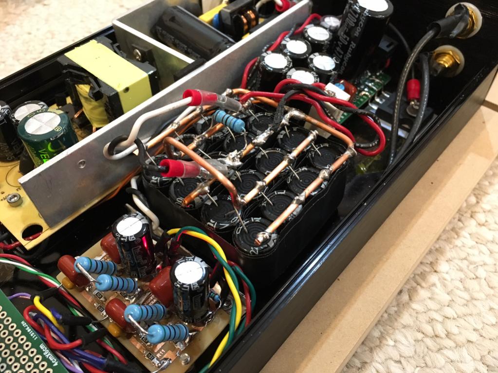
Previously I used Panasonic FC as power caps, 4700+2200uF. Replaced them with Nichicon KZ 470||470uF. Much better mids and highs without losing too much bass.
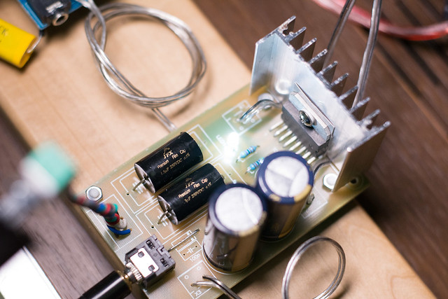
I added a preamp in front, designed by our own 'bimo', PCB by 'JOHN BALI'
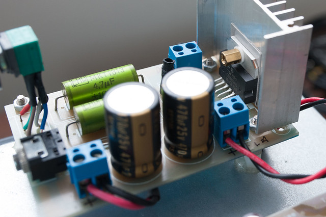
As the finishing touch, I replaced JB JFX 1.5uF with Ero 1813MKT 4.7uF.
Many thanks for everyone who helped along the way, especially Destroyer OS and Trileru.
me of these pictures have been posted here during my troubleshooting days. Now all is well and it's playing music nicely. Pardon the double posting.
Here's how it arrived from eBay:
I learned that input cap value has an impact on frequency response, and that long leads are potentially bringing RF interference.
Together with a friend designed a PCB, after a long learning curve I realized that this can be much tighter layout.
Previously I used Panasonic FC as power caps, 4700+2200uF. Replaced them with Nichicon KZ 470||470uF. Much better mids and highs without losing too much bass.
I added a preamp in front, designed by our own 'bimo', PCB by 'JOHN BALI'
As the finishing touch, I replaced JB JFX 1.5uF with Ero 1813MKT 4.7uF.
Many thanks for everyone who helped along the way, especially Destroyer OS and Trileru.
Hello, allow me to share my journey with this chip. So
me of these pictures have been posted here during my troubleshooting days. Now all is well and it's playing music nicely. Pardon the double posting.
wow, very nice...
wow, very nice...
The resolution and tone are like the LM3886 kits.
So, that could cost a BSC crossover circuit.
jwicaksana your final assembly is a thing of beauty. I use the same board u started with, replacing only 4 caps. I find the input coupling caps make the largest sound difference. The ones that sound sweetest to my ears (of the handful tried) are solen 2uF metal poly's cannibalized from an old speaker crossover. I see u are using 4.7uF input caps now; can you describe the sound difference?
Gentlemen, I appreciate the kind words. I will respond later. Right now I just bought the parts for a capacitance multiplier, and I am carrying over our discussion from the mini Karlsonator thread, I think this will benefit many of us here. X and Jon I hope you don't mind. 🙂
xrk971- I finally got the parts and assembled Juma's Easy Peasy Cap Multiplier. My hands were shaking through the whole soldering process. Luckily none of the delicate parts smoked. I'm running an HP 130 watt 19V laptop SMPS into the cap multiplier into a TDA7297 into MK 0.41X's w/ TC9FD18's. Like you said it would, the bass has improved. It's actually hard to believe the sound that is coming out of a few dollars worth of parts and 3.5" speakers. Just listened to Jaco playing on Joni Mitchell's version of Goodbye Pork Pie Hat; it was a visceral, life affirming experience and I was grinning like a kid with an ice cream cone. Two cones. You mentioned also a block of 20 or so 1000 uF cheap caps for added zest. Are they just wired in parallel? And then where do they go in the circuit exactly? Thanks again for the great guidance.
The cap array is all in parallel and goes in between the cap multiplier and the amp. Make a high current bus using solid core 12ga copper (Romex is good). Solder the 20 x 1000uF caps to the thick bus. Connect amp power leads to the bus via 16ga to 18ga copper stranded wire. The cap multiplier is needed to reduce any hum from mains. If you did not have hum then not needed. But cap Mx also provides a gradual ramp up soft start so no speaker pop from turn on.
The cap array allows use of cheap caps with typical 60mOhm ESR. 60mOhm/20 is now a 3mOhm cap ESR. That acts as essentially an infinite reservoir of charge (for a short period) so that the output transistors are never current starved. Bass impact goes way up.
You can also buy the Folsom TDA7297 PCB which has a built in cap array (Destroyer OS recommends use of Panasonic OSCON low ESR caps). So he uses fewer more expensive caps ($2ea x 10) vs my cheap bag of 50 for $3 from Aliexpress.
Here is Folsom amp for 7297:
Folsom DIY7297 Amp & Antipole PSU
Here is a photo of a 16 unit cap array with 12ga bus for a small class A headphone amp.
I don't think it is different - just use the critical part of the cap mx: the 220uF cap, 10k resistor, 1n400x diode, 220R gate stopper, 1uF and 1R5 snubber. The 4700uF output cap is optional - use whatever you have or the rail cap on the actual amp. Also, any N-channel enhancement mode MOSFET will work (IRFP240, IRF610, IRF510, etc). Even a little ZVN4306GTA and all SMT components can be used to make one that fits on a dime:
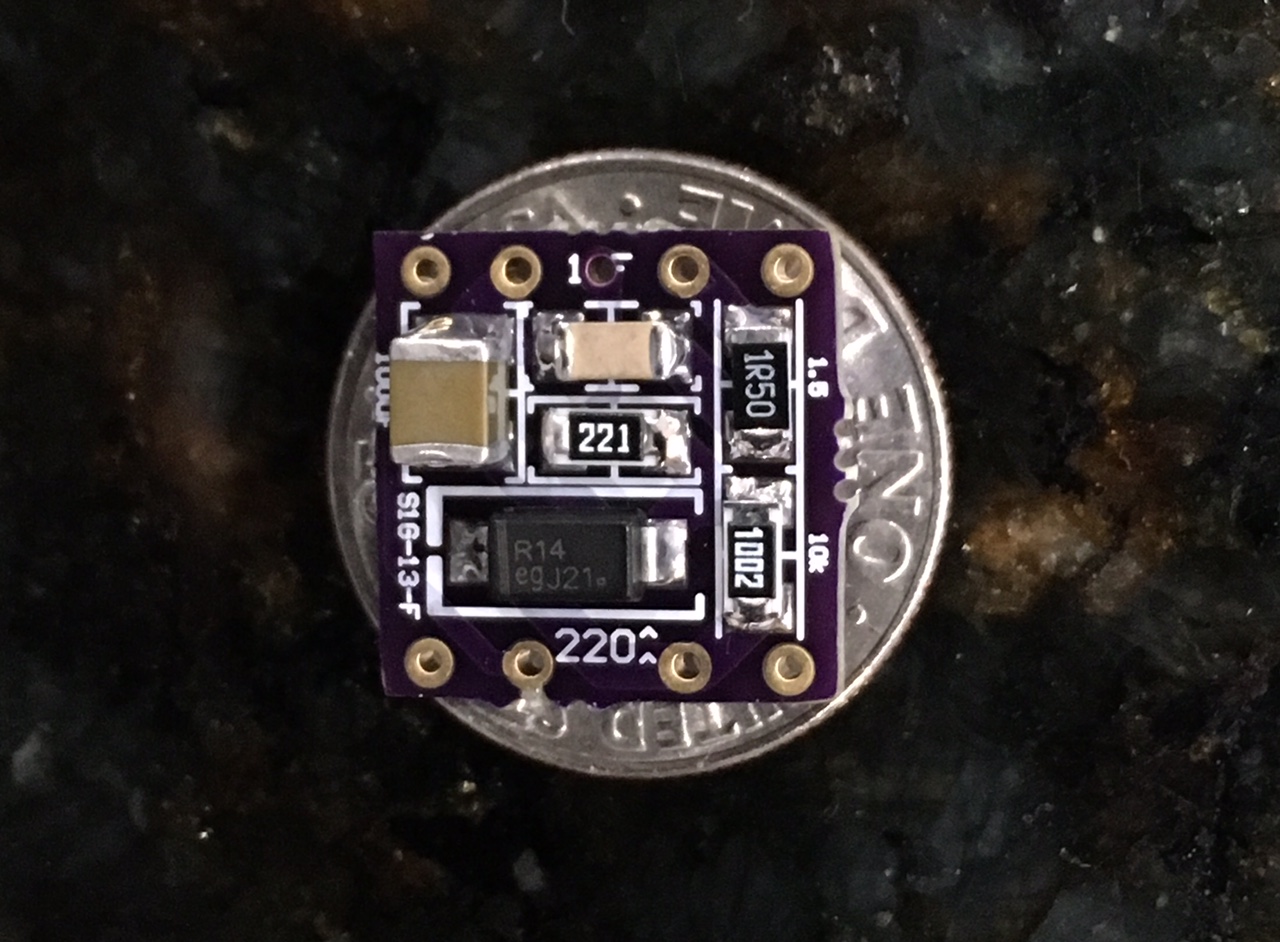
This one is courtesy of RaptoLightning who provides Gerbers for ordering your own - these are cap mx for my little pocket class A amp.
that's right. I followed xrk971's instructions as best I could. Just seven parts altogether. It would be the top right quadrant of the original schematic, minus the 4700uF cap. I used an IRF610 and a 1N4007. Put in my order for a bag of 50 1000uF caps and when that gets here I can build the cap array to complete the trifecta.
Thank you for your kind words 🙂🙂wow, very nice...
Thank you Sir. Yes I agree the input caps make a lot of difference. The bigger value (4.7uF from previously 1.5uF) brings more effortless bass, and I think I read that MKT caps emphasise certain frequency that is perceived as increase in transparency, which is what I experienced. This is now working as a system, with Muse Audio 4xTDA1543 DAC at the front. I think that this chip is sounding lush and warm and slow (subjective I know) but sweet for certain vocals and instrument. The old input cap, the JB JFX 1.5uF is described elsewhere as bright. But in my system they sounded muddy. This Ero made it transparent and balanced, BUT, without the DAC they sound tinny. Does that make any sense? Please knock me if I'm talking senseless hahaha.jwicaksana your final assembly is a thing of beauty. I use the same board u started with, replacing only 4 caps. I find the input coupling caps make the largest sound difference. The ones that sound sweetest to my ears (of the handful tried) are solen 2uF metal poly's cannibalized from an old speaker crossover. I see u are using 4.7uF input caps now; can you describe the sound difference?
Would you share your experience with different caps in this position? Thanks.
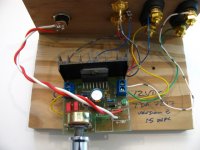
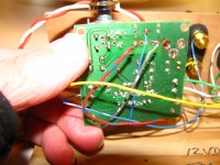
jwicaksana can you post your final assembly PCB layout, please.
I am humbled and honored, I've uploaded it here prior to photobucket madness LOL. Now my flickr won't load, I'll do it as soon as it's back to normal. Thanks!!
jwicaksana can you post your final assembly PCB layout, please.
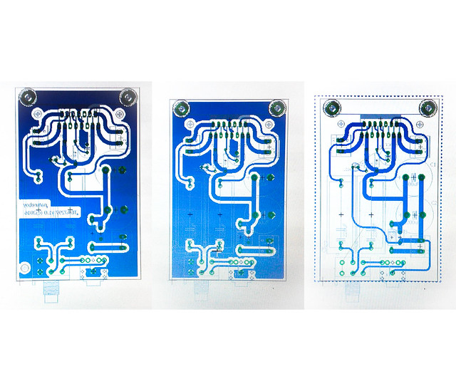
Hello zek, this is all I have, hope this helps,
I think I can recommend to you guys to build this capacitance multiplier.
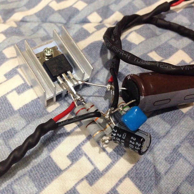
Juma's Easy-Peasy Capacitance Multiplier
Juma's Easy-Peasy Capacitance Multiplier
Nice job Jonathan. Where else can you get -45dB ripple attenuation for 7 components and all under $1.50? Btw, 1/4w resistors are fine there - no need for 1w or 2w deals.
Parts list;
- Any n channel mosfet (IRF610, 510, IRFP240, etc)
- 220uF elco cap of appropriate voltage (35v to 50v is good)
- 1uF film or X7R ceramic cap for snubber
- 10k
- 220R
- 1.5R to 10R for snubber
- any 1N400x diode
The output cap can be your usual rail cap on your amp.
P-2-P in 7 minutes. You are done, sit back and enjoy the clean hum-free sound.
Last edited:
Hi X. Thank you so much for handholding me throughout the process.
Based on suggestions from the other thread, I think I will find the time to compare the different N-MOSFET available. I tried checking the Id and Rds values and it was pretty interesting. IRF530 seemed to top the 5 and 6 family, while IRFP240 still reign supreme above them all.
What is the function of 4700uF output cap here, X?
I don't really notice any noise suppression effect, but the sound is more punchy, it is fuller, livelier, I would say. I spent about under $2 for this, so yes, awesome value for money.
Last edited:
The 4700uF cap is just a smoothing cap and serves as the chargeup reservoir of current from the mosfet. It is what gives the cap multiplier a slow ramp startup that avoids pops. If you are using a DC step up PSU and instead of 4700uF you have a huge 25,000mF low ESR cap bank (5x5 1000uF caps in parallel) the DC step up or SMPS will sometimes shut down on power up because of thinks the huge current draw from the caps is a short circuit. The cap Mx will throttle that and turn it on slowly. But once on, it can handle peak currents up to 20amps (IRFP240). This will give you even more incredible bass and rich full tones and dynamic drums. A cap bank like that can't be powered by a standard SMPS alone. Needs a cap Mx.
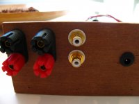
Help please. tda 7297 with no sound
I am getting no sound, and the LED is not lighting on the amp below.
I carefully and slowly removed the stock power input jack. (Yes, the amp was working before.) I have continuity on both the negative and positive wires from my new jack all the way to the board. And I get a voltage reading when I plug in my known good 12VDC supply.
I tested the LED with my meter and it lights up. I tested D2 and I see a reading there also.
As you can see, I also removed the stock input jack. I have continuity to all leads there: R input, L input, and the ground.
Any idea what I have done wrong?
Thanks everyone,
Mark
Attachments
Last edited:
Wow, the OP has such no-sound problem?
These amps are so simple that it comes down to power connection or the amp chip is dead.
Your 5.5mm barrel jack is strange looking. Are you sure you have positive polarity to the + wire to the board? It almost looks like that is the GND pin on the little jack PCB.
Have you verified +ve voltage all the way to the pin at the IC?
Yes, I am getting a positive voltage reading on the part of the board where I soldered those red and white wires. To the board, not just to the wires themselves.
If I am measuring the LED correctly, I think I got something like 3.2mV.
X, I am not certain what you mean about the GND pin on the power jack of the board. Are you wondering if the original jack of the board was set up to have the center pin as the negative, rather than the positive? I don't think that is the case, but I wouldn't know really.
I'm not sure how to measure any voltages beyond what I already have. Like to the pin of the chip.
This worked before I pulled the jack off. And I desoldered it very gently - did not force anything or ruin the board traces.
I'm puzzled. I've done stuff like this before successfully.
Thanks,
Mark
- Home
- Amplifiers
- Chip Amps
- What the heck? It's less than lunch!