Hello,Yes, I honestly think all is OK with the inductor.
Having the original transistors in place suggests the amp has never failed in such a way to pass high current through that part... and even if it had I'd still bet the part would be OK.
Quad changed the LM301 to the TL071 and that is still a good choice imo. The Quad service manual shows all the changes that occurred although I believe only the LM301 and TL071 were ever used officially.
Another to consider would be the OPA604.
everybody here seems to be ok about the good health of the L2 inductor, so :
1 - I will not change it, I will change only the caps.
2 - With the new caps, if the amp sounds nice, I will try to put in a more modern and better OP (an OPA604 seems to be the choice)
3- And finally I will adapt the output on the Pass3x valve Preamp to suit the Quad (There is MUCH more available space in a Pass3x case to put some PSB in) or I will just add a resistor in the imput of the amps, as wrote Marcel, if the result is the same.
It sounds ok for me !! 🙂
I've often thought it would interesting to modify the Quad to not use the opamp at all (as far as signal processing goes) and simply retain it as a servo.
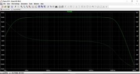
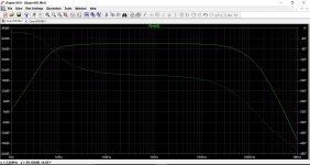
The gain would be much lower as can be seen at 15db vs around 39db for the original. If you do stick with the original version then it is very bass light by design (maybe to protect its intended partnering to the Quad ESL speakers) and so would benefit from a tweak of the time constants of the input filter.
The gain would be much lower as can be seen at 15db vs around 39db for the original. If you do stick with the original version then it is very bass light by design (maybe to protect its intended partnering to the Quad ESL speakers) and so would benefit from a tweak of the time constants of the input filter.
Attachments
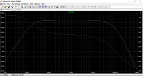
I've often thought it would interesting to modify the Quad to not use the opamp at all (as far as signal processing goes) and simply retain it as a servo.
The gain would be much lower as can be seen at 15db vs around 39db for the original. If you do stick with the original version then it is very bass light by design (maybe to protect its intended partnering to the Quad ESL speakers) and so would benefit from a tweak of the time constants of the input filter.
It looks very interesting ! And yes, this amp was made to work with ESL speakers, this is the reason of the limiter R11 on the boards. Really, what you explain here is far, far away from what I can understand in electronic building. But, as you explain it, it certainly merits to be tested.
I always wanted a Quad 405, I find it a amazing example of ingeneering and industrial design, like, in others domains... Something like some german cameras, or swiss analogic recorders or 8mm projectors. That's also why I agree to increase his sound quality by changing some obsolete components (like OP amps), but I would like to keep it for what it is, and with the kind of sound he's famous for... 🙂
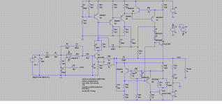
Very good explanation on how the (critical) feedback bridges works:
Quad 405-2 upgrades
by the way: agreed with others members, the inductor looks fine!
I have done some experiments with a 405 to see if I could improve the bridge balance by tuning the cap. To my surprise both channels were spot on - I could only make it worse! That to me means that probably the combination L and C has been matched to each other for each amp. This makes sense because L tolerance normally is much worse than other parts tolerance. This then means that replacing the L (or the cap) most probably will make things worse.
Jan
OK, you all convinced me that my inductor is ok ! 😀I have done some experiments with a 405 to see if I could improve the bridge balance by tuning the cap. To my surprise both channels were spot on - I could only make it worse! That to me means that probably the combination L and C has been matched to each other for each amp. This makes sense because L tolerance normally is much worse than other parts tolerance. This then means that replacing the L (or the cap) most probably will make things worse.
Jan
I will not change any value of the caps on the boards, just perhaps use 15000uF in the PSU instead of the genuine 10000 uF, I will have place for it and I could read that the bridge can stand it. And put some decoupling small caps on the transformer.
I'll have a think about the caps. I think for modern non ESL speakers it would be beneficial to get a little more flatness to the LF response. Although the lack of LF is really a combination of factors, the time constant for the servo (the 10k +100uF) is the biggest player in all this.
Ideally I would suggest going to a FET opamp such as the TL071/OPA604 and rehashing the values.
Ideally I would suggest going to a FET opamp such as the TL071/OPA604 and rehashing the values.
Mooly,I'll have a think about the caps. I think for modern non ESL speakers it would be beneficial to get a little more flatness to the LF response. Although the lack of LF is really a combination of factors, the time constant for the servo (the 10k +100uF) is the biggest player in all this.
Ideally I would suggest going to a FET opamp such as the TL071/OPA604 and rehashing the values.
all what I could read is that the OPA604 needs new diodes, the power-supply for the OPamp should be increased from 12 to 15 Volt by changing the Zener-diodes D1 and D2 with 16 Volt zeners
But to give a better response in the low frequencies, what are the the 10k +100uF you tell about ?
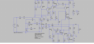
I have the last version of the 405-1, with this schematic :
EDIT : Oh, it's C2-R5 ? I didn't see your last post.
Attachments
Last edited:
That is a superb case and power transformer for a much better amp such as the Honey badger or Litchstark-x mosfet amp. both are detailed here on other threads
Both would require a DIY board made to fit the heat sink tab.
2 pair of IRFP240, 9240 will fit on that tab
if you are editing, Q3 or Q4 is redundant and creates an extra feedback pole
Faster outputs can be subbed as well
R6 = 100k and C4 = 0.47uf will lower noise and distortion
Both would require a DIY board made to fit the heat sink tab.
2 pair of IRFP240, 9240 will fit on that tab
if you are editing, Q3 or Q4 is redundant and creates an extra feedback pole
Faster outputs can be subbed as well
R6 = 100k and C4 = 0.47uf will lower noise and distortion
Last edited:
Hello Marcel,
VERY interesting !! (...) Do you think really that a simple resistor, at the input of the 405, will resolve the problems of both the input sensitivity, and the imput impedance ?
Actually I made a mistake. You have to add an RC series circuit, not just a resistor. The QUAD-405 is an inverting amplifier, so basically a current to voltage amplifier with a series resistor at its input. Increase the input resistor by putting something in series and you automatically reduce gain. To keep the bass response as intended, you also need to add a series capacitor. In fact I've done this years ago and it worked fine.
That is a superb case and power transformer for a much better amp such as the Honey badger or Litchstark-x mosfet amp. both are detailed here on other threads
Both would require a DIY board made to fit the heat sink tab.
2 pair of IRFP240, 9240 will fit on that tab
if you are editing, Q3 or Q4 is redundant and creates an extra feedback pole
Faster outputs can be subbed as well
R6 = 100k and C4 = 0.47uf will lower noise and distortion
Don't be ridiculous, that would be a terrible waste of such a technically and historically interesting amplifier.
I agree, a DIY amp can be made in a casual case for DIY projects.Don't be ridiculous, that would be a terrible waste of such a technically and historically interesting amplifier.
To dismantle a Quad 405 to put in a modern project is a cryme against this piece of history and glory of the high-fidelity. I said ! 😀
Mooly,
all what I could read is that the OPA604 needs new diodes, the power-supply for the OPamp should be increased from 12 to 15 Volt by changing the Zener-diodes D1 and D2 with 16 Volt zeners
But to give a better response in the low frequencies, what are the the 10k +100uF you tell about ?
You could increase the opamp supply voltage although I'm not sure you would gain much because the device operates at such low levels anyway.
The OPA604 can run on as high as -/+24 volts (the TL071 -/+18 as a maximum). One thing to bear in mind is that as you increase the zener voltage you correspondingly lower the current available to the zener which could result in a slight trade off in regulation. Also using opamps with higher current draw than the LM301 has the same effect.
On balance I would retain the 12 volt devices fitted.
It would probably be advisable to first of all do the recap and to make sure the original amp performs as it should, and only then look at making any changes to opamps and other areas of concern.
I say that because I know from experience on the forums that if a problem arises and to much work/alteration has been done then it becomes difficult to advise on fault-finding simply because there are to many unknowns.
Do the work slowly and methodically, listening after each set of upgrades.
Marcel and Jan... what is your honest subjective impression of the Quad ? Would it stand comparison with the best of todays designs based purely on listening or could you perhaps pick it out most times.
I'm thinking of normal domestic set ups with high quality 'normal' speakers and played at normal domestic levels.
I'm thinking of normal domestic set ups with high quality 'normal' speakers and played at normal domestic levels.
You'r right, that's what I wrote a few posts ago :You could increase the opamp supply voltage although I'm not sure you would gain much because the device operates at such low levels anyway.
The OPA604 can run on as high as -/+24 volts (the TL071 -/+18 as a maximum). One thing to bear in mind is that as you increase the zener voltage you correspondingly lower the current available to the zener which could result in a slight trade off in regulation. Also using opamps with higher current draw than the LM301 has the same effect.
On balance I would retain the 12 volt devices fitted.
It would probably be advisable to first of all do the recap and to make sure the original amp performs as it should, and only then look at making any changes to opamps and other areas of concern.
I say that because I know from experience on the forums that if a problem arises and to much work/alteration has been done then it becomes difficult to advise on fault-finding simply because there are to many unknowns.
Do the work slowly and methodically, listening after each set of upgrades.
"1 - I will not change it (L2), I will change only the caps.
2 - With the new caps, if the amp sounds nice, I will try to put in a more modern and better OP (an OPA604 seems to be the choice."
And, to be honest, perhaps if the original amp performs as it should, perhaps I will not change OPs, I don't know... As I said, I want a Quad 405, not something-better-than. My amp is all original, so I find better to keep it this way. I will change the OPs if REALLY I miss something in the sound resulting, only in this case.
But after, to try the built of a quad clone with Chinese boards and switching power supply, why not ? 🙂
Last edited:
Changing the opamp is actually one of the things that could make a big difference to the audio quality. If you fit a socket then you can try something else vs the LM301.
Have you seen the 'copy' 405 cases ?
CLONE QUAD405 chassis Power amp box DIY amplifier case L155-45 | eBay
Have you seen the 'copy' 405 cases ?
CLONE QUAD405 chassis Power amp box DIY amplifier case L155-45 | eBay
Marcel and Yoplaboum , If you want your DIY stuff to look DIY, get a kit plus tranny plus connectors etc.
I just pointed out that this amp can be had for $150 and looks far better and it's parts are better then most mid range stuff available. To modify or upgrade the existing circuit it is really no longer "Quad" anyway.
Putting a way better amp in this exceptionally quiet case forms the basis of a system that rivals a $3500 boutique amplifier.
Marcel and Yoplaboum , If you want your DIY stuff to look DIY, get a kit plus tranny plus connectors etc.
I just pointed out that this amp can be had for $150 and looks far better and it's parts are better then most mid range stuff available. To modify or upgrade the existing circuit it is really no longer "Quad" anyway.
Putting a way better amp in this exceptionally quiet case forms the basis of a system that rivals a $3500 boutique amplifier.
Why would you think the others are a 'better amp'? I haven't seen anything to give me that impression.
Jan
Marcel and Jan... what is your honest subjective impression of the Quad ? Would it stand comparison with the best of todays designs based purely on listening or could you perhaps pick it out most times.
I'm thinking of normal domestic set ups with high quality 'normal' speakers and played at normal domestic levels.
Mine is a 405-2 which has a different protection system that apparently is less intrusive, but under normal operations shouldn't engage anyway. It also has an extra bias diode to keep the dumpers on the verge of class AB, which should lower the xover distortion but I don't know how much difference it makes in practice. I find it a very good sounding amp, almost as good as my own paX amp 😉
I have also used it to drive Martin Logan Sequel II's that other amps in the same 100W/ch class had troubles with.
Peter Walker knew what he was doing.
Jan
- Status
- Not open for further replies.
- Home
- Amplifiers
- Solid State
- Bad condition of an inductor in a Quad 405