Allow two resistors in parallel for R16degen and R17degen, to provide more resistance values between standard values.
Last edited:
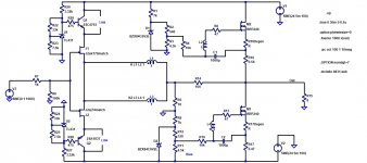
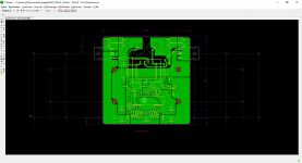
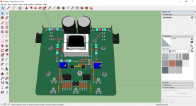
Schematics, placement.
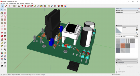
I´m using Fischer Elektronik SK490 40mm for TO92 and TO220 transistor mounting using clip.
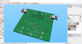
Still no information about pinning Cinemag transformer in PCB version (E24 core transformer 3D model)!
JP
I´m using Fischer Elektronik SK490 40mm for TO92 and TO220 transistor mounting using clip.
Still no information about pinning Cinemag transformer in PCB version (E24 core transformer 3D model)!
JP
Attachments

R133 R134 R124 R125 are unnecessary, although someone may prefer to set bias with fixed resistors, and use trimpot for dc offset.
If there is room you can leave them in, if you're struggling for space it would be ok to remove them.
I haven't checked pinout of jt123 flpch.
Are you sure it is pin 1 and 3 and pin 2 and 4 and not 1 and 2 and pin 3 and 4.
Looking very nice.
If there is room you can leave them in, if you're struggling for space it would be ok to remove them.
I haven't checked pinout of jt123 flpch.
Are you sure it is pin 1 and 3 and pin 2 and 4 and not 1 and 2 and pin 3 and 4.
Looking very nice.
It is likely, almost certain most people will use a value between 4k and 8k for R132 and R122 as some people required higher voltage zener diodes.
It won't change your pcb layout. Just a note so you are aware.
It won't change your pcb layout. Just a note so you are aware.
Signal to Mosfet V161 needs to be inverted, while signal to mosfet V141 should not be inverted.
Looks like you have the polarity of secondary windings the wrong way around to achieve this.
Looks like you have the polarity of secondary windings the wrong way around to achieve this.
Signal to Mosfet V161 needs to be inverted, while signal to mosfet V141 should not be inverted.
Looks like you have the polarity of secondary windings the wrong way around to achieve this.
Completely brain farted. I'll blame it on, looking at the circuit on the phone.
Your circuit is correct.
Thanks you Mr. Pass but only colours for wired version defined. Missing winding allocation to PCB pins 1 to 12.
This is the underside view from my notebook, pin 1 being on the corner
where the two pins are closer together and numbering in rotation around
the transformer so that pin 12 is across from pin 1.
Attachments


5 and 7.5mm diameter 18mm.
JP
Thank you.
I use these RFS-50V102MK9#5 Elna America | Capacitors | DigiKey
Schematics, placement.
I´m using Fischer Elektronik SK490 40mm for TO92 and TO220 transistor mounting using clip.
Still no information about pinning Cinemag transformer in PCB version (E24 core transformer 3D model)!
JP
Accessing one of the trimpots looks a little awkward with heatsink in place.
only 7.5mm lead space?
Will check trimpot placement, I´m not sure using SK490 (too high) but definitely screwed retaining springs.
http://www.fischerelektronik.de/web_fischer/en_GB/heatsinks/A06/Retaining%20springs%20for%20transistors/PR/THFM_/$productCard/dimensionParameters/index.xhtml
JP
Will check trimpot placement, I´m not sure using SK490 (too high) but definitely screwed retaining springs.
http://www.fischerelektronik.de/web_fischer/en_GB/heatsinks/A06/Retaining%20springs%20for%20transistors/PR/THFM_/$productCard/dimensionParameters/index.xhtml
JP
Waiting for comments.
JP
Have you removed paralleled resistor for degenerating?
- Home
- Amplifiers
- Pass Labs
- The diyAudio Firstwatt F6