Thank you for the schematic.I need 10amps 25-30v regulated psu , I have 2x25 v 10 amps transformer.
This schematic will work or some changes are required?
Thanks
This schematic will work or some changes are required?
Thanks
Electrocompaniet give me idea for this inverting amp.
I assume that output and driver transistors should be together on main heatsink,and that pre-drivers MJE340/350 each should have their own not too big heatsinks?
There is EX14
thank you again, mr. mile.
i didnt end up building ex14, though. 🙁
fx14 was already increasingly difficult to build for me... i would like something similar to fx8's parts count for my current project.
could it be possible to ask you for fx8 with fx14's input stage? (diamond differential? balanced ltp is it called?)
i know they were used in sansui amps and sansuis have a special memory for me, maybe thats why i find fx12 to sound so gorgeous. 🙂
oops sorry, i meant FX12
duplicate R2 and place the extra resistor before the C2 tapping.
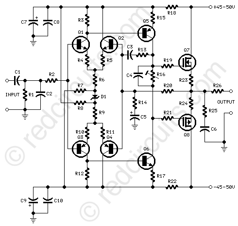
I don't like the unbalanced collector loads on the input pairs.
I don't understand R7, R8 & Zd1
Do not pass all the bias setting current through the R16 adjuster. It will not last long.
Are the outputs vert or lat?
I don't like the unbalanced collector loads on the input pairs.
I don't understand R7, R8 & Zd1
Do not pass all the bias setting current through the R16 adjuster. It will not last long.
Are the outputs vert or lat?
Its an old JLH design using ( obviously ) lateral mosfets. Despite the unpromising lack of balance in the input stages the amplifier gives remarkably good measured results with very low thd. The zener diode and associated resistors set the input stage and vas standing currents.
Relay Operated Protect Circuit
Can you please suggest me a relay operated protection circuit for AX-14 stereo version.
Good Evening Mr.Mile,Good Evening Mr. Mile,
This i made as a test amp, now I'll build a stereo version in a single board. Need some more help from you regarding protection circuit.
Can you please suggest me a relay operated protection circuit for AX-14 stereo version.
Maybe you try this protect > http://www.diyaudio.com/forums/soli...imate-fidelity-amplifier-913.html#post4913768
Attachments
Parameters amplifier APEX FH11
Hi, friends! Tell me, pleas, parameters amplifier APEX FH11 (2 pairs of output transistors). I am intrasting:
PSU nominal - ??? (V)
PSU maximal - ??? (V)
Output at 4R - ??? (W)
Output at 8R - ??? (W)
BIAS (Quiescent current of output transistors) - ??? (mA)
Thank you!
Hi, friends! Tell me, pleas, parameters amplifier APEX FH11 (2 pairs of output transistors). I am intrasting:
PSU nominal - ??? (V)
PSU maximal - ??? (V)
Output at 4R - ??? (W)
Output at 8R - ??? (W)
BIAS (Quiescent current of output transistors) - ??? (mA)
Thank you!

Hi,everyone.
This is my PCB, and I'm ready to finish it .
An externally hosted image should be here but it was not working when we last tested it.
Nice PCB
Regards
Maybe you try this protect > http://www.diyaudio.com/forums/soli...imate-fidelity-amplifier-913.html#post4913768
Thank you
- Home
- Amplifiers
- Solid State
- 100W Ultimate Fidelity Amplifier