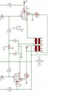
Folks, I took a little time and did a crude schematic based on the original PP 60W amp design. Lots missing and/or not quite right but I think gives the idea. On a sheet by itself is the "floating" G2 regulator. Again, lots of work to be done there but the idea is that the output cap will charge to the set point and be large enough to not droop too much during the half cycle that the circuit will be starved (when G2 current is unfortunately at its highest).
Take a look at the output side and how the upper driver gets its plate supply, so its output is properly referenced to the cathode of Vup.
Rene
Take a look at the output side and how the upper driver gets its plate supply, so its output is properly referenced to the cathode of Vup.
Rene
Attachments
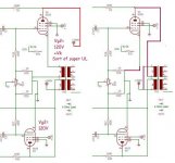
Not at all asymmetric. It is a little hard to see at first glance but it is fully symmetric. It's just that the load for the upper is physically connected to its cathode, but since the drive is between its cathode and G1, it is functioning fully as a standard common cathode stage.
The advantage here is the ability to have the two primary halves at exactly the same AC potential between any two given equivalent part of the windings. This allows for super tight coupling between them without concern for capacitance as with no AC differential, capacitance has zero effect.
That is what makes this cool If you look at where the plate resistor for the upper driver is returned, namely the plate of the lower output tube, this point is at exactly the same AC potential as the cathode of the upper tube. The upper tube's grid to cathode signal is thereby developed as in a more conventionally connected stage.
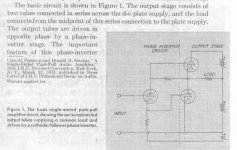
But it takes a few moments to wrap one's head around the goofy looking circuit and finally decide that it is symmetric. Not shown in this very incomplete schematic is a capacitor, large, normally connected between the cathode of the Upper and the plate of the Lower output tubes. It has DC across it but no AC. The cap is there to force equalization for any imbalances caused by any flaws in coupling. Mac used that trick. Do dig up the article by Peterson and Sinclair, General Radio Experimenter, 1951. The link was provided earlier in this thread, like the second or third post.
Thanks, Mona, for the feedback.
Rene
The advantage here is the ability to have the two primary halves at exactly the same AC potential between any two given equivalent part of the windings. This allows for super tight coupling between them without concern for capacitance as with no AC differential, capacitance has zero effect.
That is what makes this cool If you look at where the plate resistor for the upper driver is returned, namely the plate of the lower output tube, this point is at exactly the same AC potential as the cathode of the upper tube. The upper tube's grid to cathode signal is thereby developed as in a more conventionally connected stage.
But it takes a few moments to wrap one's head around the goofy looking circuit and finally decide that it is symmetric. Not shown in this very incomplete schematic is a capacitor, large, normally connected between the cathode of the Upper and the plate of the Lower output tubes. It has DC across it but no AC. The cap is there to force equalization for any imbalances caused by any flaws in coupling. Mac used that trick. Do dig up the article by Peterson and Sinclair, General Radio Experimenter, 1951. The link was provided earlier in this thread, like the second or third post.
Thanks, Mona, for the feedback.
Rene
The original splitter/driver has a boostrapped load resistor so that the top output tube performs as a grounded cathode stage also.
However, no need for two primary windings in parallel. Degrades the OT performance (2x leakage, 2x dist. capacitance of single winding) (unless each take up 1/2 the normal space and are wound as additional interleaves, so 1/2 leakage, but still 2x dist. capacitance).
The Mac OT with bifilar windings obtained 1/2 the dist. capacitance of an ordinary OT, but lost out on the the 1/2 leakage of another 2x interleave. All they really needed were the end coupling caps, no bifilar needed.
Attachments

Last edited:
The asymmetric doesn't come from the drive, that's ok, but from the screen.
The lower tube has a fix voltage in respect to it's cathode, the upper has not.
Mona
The lower tube has a fix voltage in respect to it's cathode, the upper has not.
Mona
I agree on the bootstrapping, it's what returning the driver's load resistor to the plate of the bottom output (Vlo) achieves.
On the comment about the transformer windings, I think some observations are in order.
The leakage inductance is greatly reduced, not increased, by winding the two halves in parallel. If what you are doing is comparing the single B+ arrangement to the one you posted which requires two B supplies, then you are right in saying that only one winding is actually required. But the leakage inductance is still going to be greatly reduced, if two windings are to be used, by bifilar winding them.
Now, to make sure we are both talking about the same effect, I am referring to leakage inductance between the tubes. As you know, in a conventional PP, whatever is done to increase the magnetic coupling between the two plates will have the very bad effect of increasing the capacitance between the same two plates. Not good. Dealing with leakage inductance between the primary and the speaker winding is still necessary and is solved using the same techniques of interleaving primary and secondary windings. The thing now is that the two primaries can be treated as a single winding for interleaving purposes and simplify things.
The capacitance that matters, because of the AC potentials being constant between any given part of the two windings, is not inter winding as in the common topologies, but the intra winding, which is going to be the case no matter what one does Given sufficient PA drive ability, that one is simply brute force driven and one accepts the losses. But intrawinding capacity, if anything, is lowered when going bifilar because the spacing between conductors of the same winding has been increased. With the lower supply voltage (fewer turns) and the high current capacity, this issue should have less importance than in conventional designs.
Still, what you say about using a capacitor to couple the two halves is absolutely true, and makes the need for bifilar windings really unnecessary. One advantage of bifilar windings is equal DCR for each tube, helps in keeping dynamics in balance. Plus the afore mentioned decrease in intrawinding capacitance.
I'm going to prefer the single, 260V supply approach (though the current will be quite high at 60W but, now days that is not hard to do) and the two windings to the single winding with the +/- B supply, especially as it extends toward the "rear" of the circuit. So, when I finally sit down to design the transformer and deal with all the tradeoffs, it will become clear whether to go with bifilar or not and have an idea of the intrawinding capacitance. In any case, with the coupling capacitor, it will be a great, gigantic relief to know that leakage inductance is not an issue and class B1 should be just fine.
Did I miss something?
Thanks!
Rene
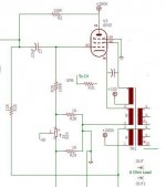
Mona, if your concern is the proper care and feeding of the upper tube's G2, that is covered in the schematic I posted. What I am calling a "floating" series regulator. My goal is to simplify, greatly, the output transformer, not add complexity to it by incorporating G2 "bootstrapping" windings.
If you have not read the article, please read it. This topology is as symmetrical as a standard P-P in terms of swing, biasing, etc, of the output tubes. There are special considerations when it comes to the drive or else the upper tube won't behave like a conventional common cathode. And the issue about not exceeding the heater-cathode voltage rating, which in this case is addressed by simply using a lower B+.
Thanks,
Rene
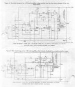
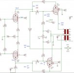
The General Radio Experimenter link shows how to put in balanced screen currents for the double primary versions (below). Screen current pathes shown on the 2nd pic. This seems to be the only reason they use the two OT primary windings, so the screen currents will balance.
Attachments
Last edited:
Yup, said so in earlier post, the reason why the final circuit will show two of the floating G2 supplies, one for Vup with its current flowing through Vup's primary winding, and for for Vlo, again with its current flowing through its winding. This way, the net DC on the core due to G2 current (and plate current also, of course) is zero and the core is happy. I'd bet if Peterson and Sinclair had had MOSFETs at their disposal back in 1951, their G2 supplies might look different.
I sure hope I have time soon to complete the schematic, values and all, and publish. I need the exercise myself to challenge things and make sure nothing has been missed.
Take a look especially at the "Schade" resistors. It is intuitively obvious that Vlo has the benefit of a traditional FB plate to plate but it took a bit of thinking to imagine the same thing happening for Vup and its driver. Do y'all see it also or am I imagining what is not there? I need to remind all that I still have not put analytical pencil to paper, this is all from the imagination to a crude schematic so far.
I know this coming week is going to be a challenge, what with the Fourth and company coming from out of town so it may be the following week.
Please y'all keep the comments and observations coming, it helps to make sure nothing is missed.
Rene
That's the GR Experimenter figure 6 scheme, which balances screen currents through the OT. But if the B+ varies, then one of screen voltages does not stay constant.
Last edited:
One tube gets B+ via a Ne-tube and the other the same thing but via the winding of the OPT.The only difference is the superimposed AC to follow the cathode.So where do you see the different influence of from B+?That's the GR Experimenter figure 6 scheme, which balances screen currents through the OT. But if the B+ varies, then one of screen voltages does not stay constant.
The idea of puting a primary winding on the cathode side is a useless complication.It looks like a cathode follower but is not.The input is between grid and cathode, not grid and ground, so no cathode feedback.Making the hole thing a half upside down PP giving the driver a hard time.One of the driver pentodes (V1B) sees a very (to) great anode voltage swing.
Mona
"So where do you see the different influence of from B+?"
Figure 6 case (top, non doubled B+):
The VR tubes both reference down from B+, under idle conditions, for the screen V's (dangerous!), with one having the winding to compensate for AC swing on the cathode. But the two VR tubes are different voltage models for top and bottom tubes due to cathode idle voltages different. They are computed for a given set of idle voltage conditions.
So if the B+ changes, the effect on the the two VR subtractions is not going to preserve either of the original screen to cathode voltages, and will affect them differently besides. (full B+ variation for bottom tube screen to cathode, and nominally 1/2 B+ variation for the top tube screen to cathode, assuming it's cathode still sits at the new B+/2) [I think..., their scheme is entirely too complicated]
"The idea of putting a primary winding on the cathode side is a useless complication."
Totally agree. They (GR E) just put that extra winding in for a convenient VR/Screen voltage scheme I think.
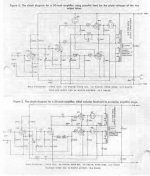
However, using the original Peterson-Sinclair single winding scheme makes for a more complex Screen V arrangement. Looks like one would use a CCS from plate to screen grid, and VR from screen grid to cathode (for each tube). But the plate V can drop below the screen V during operation (CCS not happy!), so some bootstrap capacitor from the cathode to a set of commutating diodes (max +V selecting diodes, plate V or bootstrap C voltage) to keep the CCS happy. (also an R and diode in series, between top of the bootstrap C and the plate V, for charging the bootstrap C)
The OT will perform better with just one primary winding anyway.
.
Figure 6 case (top, non doubled B+):
The VR tubes both reference down from B+, under idle conditions, for the screen V's (dangerous!), with one having the winding to compensate for AC swing on the cathode. But the two VR tubes are different voltage models for top and bottom tubes due to cathode idle voltages different. They are computed for a given set of idle voltage conditions.
So if the B+ changes, the effect on the the two VR subtractions is not going to preserve either of the original screen to cathode voltages, and will affect them differently besides. (full B+ variation for bottom tube screen to cathode, and nominally 1/2 B+ variation for the top tube screen to cathode, assuming it's cathode still sits at the new B+/2) [I think..., their scheme is entirely too complicated]
"The idea of putting a primary winding on the cathode side is a useless complication."
Totally agree. They (GR E) just put that extra winding in for a convenient VR/Screen voltage scheme I think.
However, using the original Peterson-Sinclair single winding scheme makes for a more complex Screen V arrangement. Looks like one would use a CCS from plate to screen grid, and VR from screen grid to cathode (for each tube). But the plate V can drop below the screen V during operation (CCS not happy!), so some bootstrap capacitor from the cathode to a set of commutating diodes (max +V selecting diodes, plate V or bootstrap C voltage) to keep the CCS happy. (also an R and diode in series, between top of the bootstrap C and the plate V, for charging the bootstrap C)
The OT will perform better with just one primary winding anyway.
.
Attachments

Last edited:
That doesn't come for free either. Leakage inductance decreases (with very good approx.) with the square value of the number of interfaces while capacitance increases proportionally to the numer of interfaces and that is good thing. However the process cannot be used at will because too much interleaving will bring some additional leakage and (at some point) un-acceptable copper loss as you waste more winding space for insulators. If you increase the size of the transformer capacitance will increase according to surface....Dealing with leakage inductance between the primary and the speaker winding is still necessary and is solved using the same techniques of interleaving primary and secondary windings.
A transformer is always a compromise among several contrasting requirements as everything else....
This is pretty much theory. In practice a PP transformer can be done without compromises without split bobbins for the two primary halves while getting Rdc balance within 1% very easily and better coupling. With some attention quite less than 1%! 1% is a tolerance far better than any other in the amp.One advantage of bifilar windings is equal DCR for each tube, helps in keeping dynamics in balance.
Did I miss something?
Thanks!
Rene
From my perspective, it would be better to design the amp to work fine with a variety of actual loads rather than maximizing power into a nominal load, unless one has a flat impedance "easy-to-drive" loudspeaker which would be fine.
So, for generic application I would like to get those 60W into the most demanding load I want to drive. I think this is a more effective approach than mere class A, class AB or class B discussions...
Woops, late edit to post #36
The Fig. 6 (top diagram) output tube cathodes are both DC referenced to ground (not to B+/2 as I mentioned for one of them), but the VR tube values are slightly different to compensate for the DC winding resistance for the top tube (x idle current). So the screen voltages will still mis-track -slightly- (change in idle current thru the winding R) with B+ change. But mainly, the Screen V for both tubes changes directly with B+, not good.
The Fig. 6 (top diagram) output tube cathodes are both DC referenced to ground (not to B+/2 as I mentioned for one of them), but the VR tube values are slightly different to compensate for the DC winding resistance for the top tube (x idle current). So the screen voltages will still mis-track -slightly- (change in idle current thru the winding R) with B+ change. But mainly, the Screen V for both tubes changes directly with B+, not good.
Last edited:
As you can see, the anode V1B has to drop well under zero to give the output tube the nessesairy drive.Since that's not possible forget the hole thing.
Mona
Mona
Oh, that driver voltage.
The original Fig. 6 design has a bootstrap resistor load for the Concertina plate. So the new differential driver would need a bootstrap load from the bottom output tube plate.
Oh, it has one already, R19. But not making the correct range yet. Those "Schade" resistors just add to the complications. Hmm, R2 is not working correctly for a "Schade" resistor? No, I guess it is. The top output tube is living in its own relative world up there. I assume V3 plate is connected to +260V. (line missing)
So V1b plate needs a CCS pull-up to get the driver plate voltage range shifted up. OR, R2 needs to be connected to a higher B++ to fix the voltage.
Last edited:
- Status
- Not open for further replies.
- Home
- Amplifiers
- Tubes / Valves
- 60W With Sweep Tubes, Different Topology