Locking for a Simple Class B or AB Mosfet Amp schematic
Hi. I am locking for a schematic of a simple class B or AB mosfet amplifier.
I found one which I thought was the ideal, with IRF540/IRF9540, but it does not work.
Someone knows a schematic of a simple (1~2 transistors + 2 mosfet - preferably IRF) class B or AB mosfet amplifier that works? 20~30W is enought.
The use is for guitar.
Thanks.
Last edited:
Not surprised that circuit doesnt work, its dreadful...
https://sites.google.com/site/quasisdiyaudiosite/nmos-series/nmos200-1
https://sites.google.com/site/quasisdiyaudiosite/nmos-series/nmos200-1
Hm, Quasi's circuit is more complicated than you'd like - but you dont get much less complicated than his design without it being an unreliable pile of sh*t
Yes... unfortunately more complicated than i´d like and much more powerfull than i need.Hm, Quasi's circuit is more complicated than you'd like - but you dont get much less complicated than his design without it being an unreliable pile of sh*t
But thanks for your reply...
Output power is a matter of the voltage you feed it. You could run the NMOS200 on +/- 25V supplies easily.
If you want a "simple" amplifier, build a chipamp. LM3886 is fine for low power guitar duty and is even used by some of the big names for this purpose.
If you want a "simple" amplifier, build a chipamp. LM3886 is fine for low power guitar duty and is even used by some of the big names for this purpose.
BD512/522 are ancient vertical MOSFETs. IRF are HEXFETs and as there is no thermal compensation so the amp will overheat and fail. Even if this circuit does work, it's sound quality will be very poor.
...there is no thermal compensation so the amp will overheat and fail...
Not necessarily, if the bias is low enough and the heatsink is big enough, than thermal runaway should not happen, especially with mosfet devices.
Kem try this one:
An externally hosted image should be here but it was not working when we last tested it.
It should do the trick.
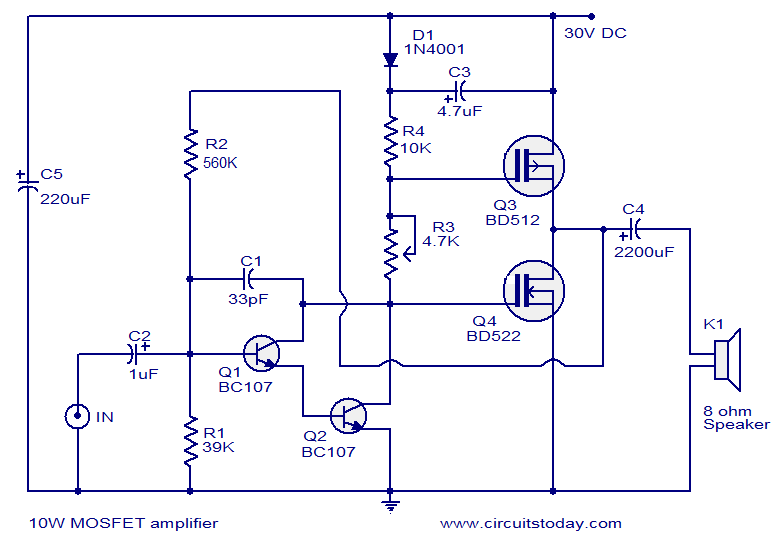
R4 is for setting the midpoint between the mosfets ( the output before the capacitor ) at half the Vcc. R11 is for biasing the mosfets, you could replace the zener diode with a couple more of 4148 and fixing them to the heatsink in some way, should give you some thermal compensation for the bias. You may have to increase R11's vallue to be able to get proper bias.
Good luck.
Last edited:
MarianB, thanks for the schematic.
One question... why 47R as load?
And C1 is not polarized, right?
One question... why 47R as load?
And C1 is not polarized, right?
Last edited:
Indeed the load value is wrong, sorry about that, in my hurry to draw you the schematic i missed that... The load can be anything from 4 Ohms up.
Yes, C1 is not polarized if possible, at minimum 16V.
Yes, C1 is not polarized if possible, at minimum 16V.
You're definitely going to want a preamp in front of that circuit as it's input impedance is rather low. Im still not convinced, but perhaps the distortion will give a pleasing sound for guitar use.
Never mind... You are helping me a lot.Indeed the load value is wrong, sorry about that...
But... another question... what is the function of C1?
Can i use this one?

Last edited:
Certainly!!! And this is the ideia...You're definitely going to want a preamp in front of that circuit
Yes, you can use that one ( i see 106 code on it ).
C1 reduces the AC impedance of the biasing network ( D1, D3 and R11 ), thus making sure the output devices see about the same signal. It's value is not fixed at that 10uF, it can be less without any problem, but 10uF at low voltage is quite cheap, so...
About the input, it needs about 1V peak to fully drive it ( 0.707Vrms ), so the signal source amplitude should not be a problem, but you do need a low output impedance source, so i would recommend using either an opamp preamplifier or if you need to use a transistor preamp, then you can use an opamp buffer.
Feel free to ask anything you need to know 🙂
Last edited:
106 (=10uF) in that size must be a HiK ceramic.
HiK ceramic are not recommend for passing audio signal.
HiK ceramic are not recommend for passing audio signal.
It will mainly pass trough that cap, i still think you can use it, the overall performance is not high enough for that cap to make a difference. I am sure you will enjoy the end result.
Maybe i did exaggerated a bit earlier, but it does speed's up the turn off process of the output devices so i guess you could say it passes some of the signal, thus it is important, but not mandatory.
As I understood, the audio signal will not pass through the capacitor...
post1 schematic shows C1 as the DC blocking capacitor on the signal input line.C1 it is not in series with the signal.
C1 passes audio signal and blocks DC.
- Home
- Amplifiers
- Solid State
- Simple Class B or AB Mosfet Amp