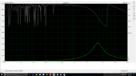
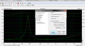
I don't think so: The shape of the curve at the right is very weird and this is not a good symptom regarding your test jig/calibration.
The impedance curve at the right should be monotonously rising and it is not.
Have you tested the impedance of your test jig in itself before any measurement? Are you compensating for cable impedance?
I once found a problem with the inputs of a soundcard i used in the past and gave similar anomalies.
Other sanity check, have you tried to measure the inductance of an air core inductor you know the specs?
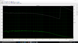
It's obvious you have a problem with calibration and/or test jig.
Impedances above 1k should not fall that way, constantly rising for an inductor and flat for resistor.
Probably your 1 ohm resistor measures apparently flat because of the huge vertical scale...
Impedances above 1k should not fall that way, constantly rising for an inductor and flat for resistor.
Probably your 1 ohm resistor measures apparently flat because of the huge vertical scale...
![WP_20170328_001[1].jpg](/community/data/attachments/560/560519-4e452c378addfb0ffe22f56706d7dfec.jpg?hash=TkUsN4rd-w)
![WP_20170328_002[1].jpg](/community/data/attachments/560/560533-210746fe055f98efce5bf6ed59f91d33.jpg?hash=IQdG_gVfmO)
Btw, contrary to Le, Re is not frequency dependant but simply the value of voice coil resistance at dc.
You can get this with an ohmmeter or let Limp estimate the value at the Analyze / Loudspeaker Parameters. You don't get there the value of Le at any reference freq, as Limp offers instead a model for the inductive behaviour of the voice coil to account for dependance on frequency.
Once again if you only want to plug Re and Le values into some magic formula to calculate a Zobel, it's a bit confusing, but you should always get an acceptable flattening of the impedance.
Once again, all these things are dead boring, aproximate and unncessary...
I'm sure latest drivers don't support:
"Note that Windows 8 (or later) is not compatible and will not be qualified"
"Note that Windows 8 (or later) is not compatible and will not be qualified"
Felipe, the measurement in your post #20 can't be true for you have a driver of Re=5,6 and the Z at 200 Hz is about 4,5. That can't be for a unit that's not low passed. All in all, this inductance business at 1 kHz isn't that important as is the impedance plot in general because you should rely your simulation/design on the factual data. I don't see a reason not to go to ARTA thread and seek guidance. Study the LIMP manual once again.
VaNarn, you weren't paying attention to my measurement of SS 13M 8640-00. I didn't photoshop these values! It's real data for the units I had at hands, and Audiomatica Clio calculates as I have already said. I have one book on speaker design, and there is also the same procedure for calculating voice coil inductance at a frequency of our interest. There is no wrong or right formulae! The right triangle mathematics is simple.
edit: I'm attaching original text file measurement, with phase angle.
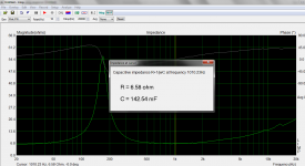
I am gratified to see that you have the Clio system with a NotePad function. Using the entries from this for 1kHz,, I calculate that L=51.4 micro Henry for a Z of 7.2 ohm (phase 2.57 degrees) and Re(f) is 7.19 ohm.
At 10kHz, L= 40.5 micro Henry for a Z of 8.95 ohms (phase 16.52 degrees) with Re(f) being 8.58 ohm . I believe an amendment to your book is required.
Last edited:
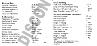
How do you explain the fact that Scan Speak published a value of Le=0,1 mH for SS 13M8640-00? Looking at your way of calculating this, neither 10 kHz is close to that figure, nor the 1 kHz! And yet you can see from Clio TS parameters evaluation measurement that measured Le =0,11 mH at 10 kHz.
edit: I have included a traced impedance of Seas CA 18 RLY and these guys calculate Le not by theta, but Xl=sqrt(Z^2-Re^2) which gives Le about 1,01 mH ( officially 1,05 mH). Other manufacturers ( Audio Technology) calculate by theta.
edit: I have included a traced impedance of Seas CA 18 RLY and these guys calculate Le not by theta, but Xl=sqrt(Z^2-Re^2) which gives Le about 1,01 mH ( officially 1,05 mH). Other manufacturers ( Audio Technology) calculate by theta.
Attachments
Last edited:
I've noticed in the text file just above that the negative phase angle slipped into HF data because downsloping FR curve got caught in tracing. The 1 kHz data remains okay.
my measurement of SS 13M 8640-00.
I got for that data in my simple impedance fitting spreadsheet...
Fs=120
Qts=0.59
Qes=0.68
Cmes=0.000148
Lces=.01186
Res=37.8
L1=37uH
R1=6.1ohms
L2=.34mH
R2=2.4ohms
Cmes, Lces and Res are all in parallel
L1 and R1 are in series with the above, you could consider these representative of Le and Re in the fit
L2 and R2 are in parallel, in series with L1 and R1, these model the lossy inductance
There is no such thing as "Le", it varies with frequency and is a mostly useless concept.
Last edited:
It's actually quite impressive what mathematical simulators do with lumped parameters.
I mean, conjugate THAT? 😀
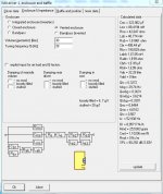
The below sample is how Visaton Boxsim actually tries to find some understanding of the sort of bass impedance connected to an amplifier. It evidently works at some level. But, honestly, I wouldn't bet my life on the theory.
Especially with SB Acoustics or Scanspeak drivers. Which seem to be more about the money than the theory.
I mean, conjugate THAT? 😀
The below sample is how Visaton Boxsim actually tries to find some understanding of the sort of bass impedance connected to an amplifier. It evidently works at some level. But, honestly, I wouldn't bet my life on the theory.
Especially with SB Acoustics or Scanspeak drivers. Which seem to be more about the money than the theory.
Attachments
The error occurs as the D.C. resistance is being used in the calculation. If you measure a series circuit containing an inductor and a resistor at D.C. you would not expect to have a reading for Xl. Do you not trust your NotePad figures for Z and phase degrees for the SS 13M 8640 ? Remember Re(f) =cos theta.Z at the reference frequency and Xl = sin theta.Z at the same freq. Note Re(f) is not Re although they both are on the same real axis. Re(f) be it noted again, is a variable with frequency.
I cannot explain the discrepancies that manufacturers incur with their Le figures. It may be down to the measurement programs that they use: typically 1kHz appears to be the default frequency in common use. Alas, perhaps they too are basing their calculations on the voice coil D.C. resistance.
The first method that I tried to determine a phase angle measurement was with a CRO using a Lissajous figure ellipse, circa 1965. Awkward, but with care gave reasonable results. I later built a Grutzmacher bridge from a cct. from a Bruel & Kjaer catalogue which gave more precise readings. Computer programs are much more convenient. The method of calculating the correction components to flatten a speakers inductive impedance, was derived from "Alternating Current Theory" Volume 3 by G.N. Patchett. Years later the equation for a Zobel network i.e. C= Le/Re^2 intruded on the speaker scene without any explanation of how it was formulated. It was borrowed from a method of preventing high voltage breakdown of O/P transistors in amplifiers. It should be ditched and it is unfortunate that it appears in many text books that otherwise are free from blemish.
Last edited:
The error occurs as the D.C. resistance is being used in the calculation. If you measure a series circuit containing an inductor and a resistor at D.C. you would not expect to have a reading for Xl. Do you not trust your NotePad figures for Z and phase degrees for the SS 13M 8640 ? Remember Re(f) =cos theta.Z at the reference frequency and Xl = sin theta.Z at the same freq. Note Re(f) is not Re although they both are on the same real axis. Re(f) be it noted again, is a variable with frequency.
Obviously, no manufacturer specifies a frequency dependent Re(f) value. All loudspeaker and inductor manufacturer specify a fixed Re value measured at DC.
If this dc value is not known, it can be aproximated from an impedance measurement ( RLC) like those provided by Limp.
In the TS param estimation menu you can choose between both methods for Re. But obviously each method gives also a diferent value for inductance values.
Question is: the only REAL thing here is Re at DC, all the rest is pure fiction, principally the voice coil inductance which is NOT a pure inductor.
Attachments
Last edited:
Speaker measurements are made with the voice coil moving.
GDO you are on the road to nowhere. You are only repeating what is common knowledge and making serious errors ,as well. D.C. resistance is measured with a precision multimeter, preferably with the voice coil blocked for accuracy. End of story . Everything else is a dynamic measurement and so the various factors are frequency dependant Can I point you in the direction of the Smith & Larson Woofer Tester that will calculate the correction circuit directly without the need of using formulas. They certainly have woken up to the mistakes of the past.Obviously, no manufacturer specifies a frequency dependent Re(f) value. All loudspeaker and inductor manufacturer specify a fixed Re value measured at DC.
If this dc value is not known, it can be aproximated from an impedance measurement ( RLC) like those provided by Limp.
In the TS param estimation menu you can choose between both methods for Re. But obviously each method gives also a diferent value for inductance values.
Question is: the only REAL thing here is Re at DC, all the rest is pure fiction, principally the voice coil inductance which is NOT a pure inductor.
GDO you are on the road to nowhere. You are only repeating what is common knowledge and making serious errors ,as well. D.C. resistance is measured with a precision multimeter, preferably with the voice coil blocked for accuracy. End of story . Everything else is a dynamic measurement and so the various factors are frequency dependant Can I point you in the direction of the Smith & Larson Woofer Tester that will calculate the correction circuit directly without the need of using formulas. They certainly have woken up to the mistakes of the past.
Buff, YOU look like a pure stubborn resistor with its neurones blocked by some automatic correction device... No drift ensured!😀
- Home
- Loudspeakers
- Multi-Way
- Calculating driver inductance from Limp