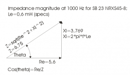
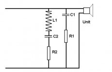
Ah, the inevitable re-appearance of that piece of nonsense formula for speaker impedance correction, falsely attributed to Zobel. The correct method to obtain a flat impedance with minimum phase i.e. the speaker will look like a resistance in the crossover frequency range is to use Boucherot's method for power factor correction. This involves finding the impedance and phase of the speaker at the crossover frequency and solving for R=cos theta.Z and for XL= sin theta.Z From this information vector formula methods are used to resolve the distribution of current in the correction circuit to find the values for C and R. The Smith & Larson Woofer Tester will do all this for you, if you are not familiar with the maths involved.
The earliest reference that I have for the Zobel network formula is from a Philips/ Mullard book, "Transistor Audio and, Radio Circuits", circa 1969. It was given as a precaution against high breakdown voltages of output transistors that could be caused by an inductive speaker load. The formula given was Cz= Ls/Rs^2. Later clones of this calculation in an attempt to flatten a speakers' impedance use Rdc or Re x 1.25 in attempt to correct for the nominal impedance (Z) of the speaker to suit a crossover network design. By example using a Focal 7N313 where the D.C. resistance is given as 6.1 ohm and the inductance as 0.38 mH ( at 1 kHz ?) the first formula gives Cz as 10.21 mFd and the latter as 6.536 mFd. Using the method outlined in my first post the impedance at 3.5 kHz ( the desired xover freq.) was found to be 10.34 ohms with a phase angle of 28.65 degrees. This gives the effective resistance as 9.0742 ohms and the inductance as 0.2254 mH . Calculating for a network to give an impedance of 8 ohm with the phase at 0 degrees in conjunction with the speaker, resulted in values of 10.67 ohm and 3.69 mFd. It is a pity that many sources still keep quoting the wrong method of correction and so many people have been caught by this misapplied Zobel network.
Theta is the angle value to be flattened?
I don't see a point in using any Zobel formula without the simulaton of driver response and impedance. As far as I remember, Zobels come in handy with high Le drivers. Simulation software is nowadays very common tool and simple to use and it's the greatest tutor you'll ever find and still people would rather believe in all else than what's important. Sketch is good for principle only.
Attachments
Last edited:
Felipe, this is the thread.
http://www.diyaudio.com/forums/multi-way/76977-arta-55.html#post5000040
Thank you.
There is no "correct" formula for a Zobel network.
The goal of the crossover is to achieve a target electroacoustic transfer function. Given that no driver ever made has perfectly flat frequency and impedance response, the values in the Zobel circuit are tweaked to adjust the resulting transfer function.
The goal of the crossover is to achieve a target electroacoustic transfer function. Given that no driver ever made has perfectly flat frequency and impedance response, the values in the Zobel circuit are tweaked to adjust the resulting transfer function.
It's all woolgathering without a clear idea where you are heading. 😀
Michael Chua does a bass filter with impedance correction here:
Seas ER18RNX with 27TDFC
Loosely based on the BBC design for the LS5/9:
Rogers Loudspeakers › LS5/9
Pretty good calculator here:
mh-audio.nl - Home
Bafflestep implemented passively. Very clever, IMO. You can equalise the tweeter too.
Michael Chua does a bass filter with impedance correction here:
Seas ER18RNX with 27TDFC
Loosely based on the BBC design for the LS5/9:
Rogers Loudspeakers › LS5/9
Pretty good calculator here:
mh-audio.nl - Home
Bafflestep implemented passively. Very clever, IMO. You can equalise the tweeter too.
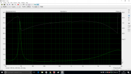
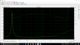
With Zobel 3.9uF 6R8 without LP filter, yellow without zobel, green with zobel.
Attachments
Last edited:
It's all woolgathering without a clear idea where you are heading. 😀
Michael Chua does a bass filter with impedance correction here:
Seas ER18RNX with 27TDFC
Loosely based on the BBC design for the LS5/9:
Rogers Loudspeakers › LS5/9
Pretty good calculator here:
mh-audio.nl - Home
Bafflestep implemented passively. Very clever, IMO. You can equalise the tweeter too.
Thanks for the links, very useful.
SB Acosutic SB23NRXS45-8 8"
Attachments
Calculator gives 7R & 12.24uF
Hmm, curious. 5.6R and 0.6mH Le. Which is low for a big bass.
8'' SB23NRXS45-8 :: SB Acoustics
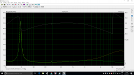
7R and about 6uF seems to work better. Damping rings seem to be reducing inductance more at high frequency. I suppose you'd expect that. This stuff is a bit rough and ready anyway. But I'd trust the modelling.
Le is very frequency dependent, and a Zobel is not the last word. People have done more complex things. But a RC should be good enough.
8'' SB23NRXS45-8 :: SB Acoustics
7R and about 6uF seems to work better. Damping rings seem to be reducing inductance more at high frequency. I suppose you'd expect that. This stuff is a bit rough and ready anyway. But I'd trust the modelling.
Le is very frequency dependent, and a Zobel is not the last word. People have done more complex things. But a RC should be good enough.
Attachments
Yes Felipe, these look realistic, with some issues at very high frequencies. Could you measure the raw woofer unit out of the enclosure without Zobel, set on the floor and export it to a .txt file here? And check the Re with a multimeter set to show DC resistance. If this is too much hassle, nevermind.
Last edited:
Perhaps these Zobel calculators weren't designed to include damping rings! 😀
AFAIK, the reason the resistor is 25% bigger than the DCR is to include the mechanical losses of the speaker. I've never spent time on the more complex correction.
But if in doubt, I'd go smaller on the capacitor. It's certainly a neat way to do things. Impedance corrected, all those old standard crossover calculators work on values:
https://www.diyaudioandvideo.com/Calculator/SpeakerCrossover/
Doesn't include bafflestep, of course.
Last edited:
Hmm, curious. 5.6R and 0.6mH Le. Which is low for a big bass.
8'' SB23NRXS45-8 :: SB Acoustics
7R and about 6uF seems to work better. Damping rings seem to be reducing inductance more at high frequency. I suppose you'd expect that. This stuff is a bit rough and ready anyway. But I'd trust the modelling.
Le is very frequency dependent, and a Zobel is not the last word. People have done more complex things. But a RC should be good enough.
Troelsgravessen does for the same woofer 1st order LPF 600Hz + RC zobel. Link: http://www.troelsgravesen.dk/SBAcoustics-3WC.htm

Last edited:
HaHa, deconstructing a crossover. Very naughty, and something I enjoy. 😀
SBAcoustics-3WC
I'd guess that bass circuit is around 3.9mH with a 56uF and an ohm or two to align phase! Not a Zobel at all. But Troels uses an Le of 0.15mH in his sim. What you do is align the target curve with your sim to see if it does the right things.
SBAcoustics-3WC
I'd guess that bass circuit is around 3.9mH with a 56uF and an ohm or two to align phase! Not a Zobel at all. But Troels uses an Le of 0.15mH in his sim. What you do is align the target curve with your sim to see if it does the right things.
- Status
- Not open for further replies.
- Home
- Loudspeakers
- Multi-Way
- Zobel