I can agree with you that BN can exists without a hysteresis loop, even more, it can exists with a constant external magnetic field, even more, it can exists without an external magnetic field, any mechanism which can produce magnetic domain avalanche can produce BN, e.g. mechanical stress, but it cannot exists a magnetic hysteresis curve without BN, so you cannot say that BN has nothing to do with magnetic hysteresis.You lost the original sense of that. The order of magnidute is not referred to the peak itself but is a comparison with the other method relying on minor loop with no zero-crossing instead of B-H loop that you didn't like. You can see both in the article I posted! Here in town a 2 mV RMS of the peak is of the same order of 0.5mV RMS of the minor loop. An order of magnitude is a factor of 10. There is only 1 case out of 6 where it is almost there but there are 4 where it is not even a factor of 2! And this is not transformer core material, yet...
You put a picture of un-specified material where the peak value is in the volt range to compare with the real thing (GO laminations) that displays a signal 3 order of magnitudes lower! Unfortunately your picture refers to out-of-service steel pipelines (possibly also with poor magnetic properties) that very likely had a lot of stress and all sorts of defects or even damage. Of course BN signal was so big.
So far you have been quite correct, except perhaps for some precipitate calculations and other details, but this nonsense about the order of magnitude it is not worthy of you, so I will ignore it.
As I said before, it does not matter if it was a steel pipeline or a can of sardines, if they are ferromagnetic they must exhibit BN, and if you measure BN in a hysteresis loop it must have well defined peaks around zero crossing, in the paper of post #23 there are not, as I suspected due to differential coil, your posted paper is correct in this sense, although the guys have not a clue about metric units, can you imagine a power transformer working eleven years at 520ºC? Can you imagine a magnetic lamination of 7mm thick? Here in town there is a guy who makes power distribution transformers, and I can assure you that his lamination is a black GOSS less than 0.25mm thick, it would be the envy of Hashimoto san.
Finally, along the whole thread you have been fiercely clinging to BN values from papers, as it would exists some BN pattern; it is not by chance that most values are consistent, this can be explained by the need of researchers on comparing their work. So does exists some BN pattern? Where?
Last edited:
Post#23 reference:
Section 5.3: "One search coil technique rather than a double coil arrangement is used to avoid losing some Barkhausen events in the subtraction process [5.7]."
I reckon the earlier reference to a 2x 80 turn search coil in Section 5.2 may have been his starting point, but a 500T single coil may have been his final search coil for results.
I can't see any part that identifies a lamination is 7mm thick ??? There are lots and lots of appropriate thickness references, including eg.
Section 5.6.1: "Thickness of the sample: A digital micrometer was used to measure the thickness and its accuracy was 0.0025 mm, which is 0.83% of the 0.30 mm thick sample."
Section 6.2: "This part of the investigation was carried out on samples of HGO and CGO steels, 305 mm x 30 mm x 0.27 mm from Cogent Power Limited United Kingdom. 40 strips comprising 20 CGO and 20 HGO were tested."
I can agree with you that BN can exists without a hysteresis loop, even more, it can exists with a constant external magnetic field, even more, it can exists without an external magnetic field, any mechanism which can produce magnetic domain avalanche can produce BN, e.g. mechanical stress, but it cannot exists a magnetic hysteresis curve without BN, so you cannot say that BN has nothing to do with magnetic hysteresis.
I think it's clear what I meant and I was referring to the magnitude of BN signal. I never wrote "BN has nothing to do with magnetic hysteresis" I wrote it has nothing to do with hysteresys derivative in the sense that you can't tell anything about its magnitude just looking at Hc, permeability and other macroscopic parameters.
In fact in the article I linked one can see: 1) there are 2 steel alloys; 2) For each alloy there are three variants; 3) The variants with highest permeability-lowest Hc and lowest permeability-highest Hc have BOTH less noise than the other one.
I don't think I have been fierce. It's not me insisting on inexistent issues!
I really don't know if there is pattern what I know by experience is that zero crossing and Barkhausen noise are not problems at all in valve audio amplifiers.
So the solution to eliminating xfmr distortion and noise is low drive impedance.
Unfortunately, this is the most common failing of SE designs with excessive triode output Rp. Some local N Fdbk can fix this of course.
So tube output Z is the real issue for either SE or P-P. High permeability makes it easier for the tube due to lower magnetizing current to deal with.
Thanks Ive had a strong feeling that the above statements are true for quite some time.
TM
No Tim, wrong paper, anyway section 5.2 at page 52Post#23 reference:
Section 5.3: "One search coil technique rather than a double coil arrangement is used to avoid losing some Barkhausen events in the subtraction process [5.7]."
Two 80 turns search coils connected in series opposition and would around a plastic carrier slid provided a differential signal feed to a National Instruments (NI) 4552 AD card with a resolution of 16 bit, sample rate of 204 kHz and 95 kHz bandwidth. The output signal at 50 Hz from each coil was of the order of 200 mVrms (at 1.4 T) and comprises a dominant Faraday emf component and the low level (in micro volts range) Barkhausen signal so by connecting in series opposition the Faraday emf cancels out and the voltage fed to a personal computer (PC) mainly comprised the Barkhausen noise component [5.2].
I will repeat, BN measured along a hysteresis loop must have peaks around zero crossing; there are no peaks in this paper, so the author used a differential coil, as BN is not entirely random, the peaks was cancelled.
Then the author lied, even worse, he used the same standard set-up
https://www.researchgate.net/public...g_technique_on_interpretation_of_measurements
Wrong paper again, just seeI can't see any part that identifies a lamination is 7mm thick ??? There are lots and lots of appropriate thickness references, including eg.
http://ac.els-cdn.com/S030488531400...t=1486052585_2d0df69aa4616075cd7af0b99f1c587f
At section 2.2
Maybe they did not use transformer lamination…Both steels were taken from components removed from service for approximately eleven years at 520 °C. Selected samples (approx. 70 mm×15 mm×7 mm) were heat treated to simulate service entry microstructure
So no reason to take paper measurements like a gospel and making S/N calculations as if existed a pattern.I really don't know if there is pattern
Simple experiments on the web suggest that BN is relevant for audio, I did not know that, but BN admits a FFT and my guess is that BN is masked on the FFT.
No!! How many more times do I have to tell you that moving a domain wall involves flipping some spins, not flipping a domain? Is it so difficult to understand? Your argumentativeness is consistent with you not knowing what is meant by a magnetic domain. If you want to call this 'flipping part of a domain' then you are just adding confusion.popilin said:To move a domain wall, it must flip the neighbor domain, or part of it if its intrinsic magnetic moments are strong enough.
Is this so difficult to understand?
Simple experiments on the web suggest that BN is relevant for audio, I did not know that, but BN admits a FFT and my guess is that BN is masked on the FFT.
Some simple web suggestions are irrelevant because it is not core material used in audio transformers, becuase there is no transformer, because there is no amplifier to amply the BN noise.
If you use any random magnetic material that has a lot stress and defects the noise it can generate can easily be 3 order of magnitudes higher (As you can see in the picture you uploaded). That's 60 dB higher. And still you need to amplify it to hear some tiny random noise in a dead quiet enviroment.
So no reason to take paper measurements like a gospel and making S/N calculations as if existed a pattern.
The papers are usefel to assign things the right magnitude!
The gospel is what I hear. I use valve amplfiers EVERYDAY. There is no such noise and these are not noisy amplifiers by any standard. The last one I have made has fully regulated supply with 0.2 mV ripple.
Last edited:
Some simple web suggestions are irrelevant because it is not core material used in audio transformers, becuase there is no transformer, because there is no amplifier to amply the BN noise.
Right now I finished my BN experiment, 60 pcs. GOSS 114mmx19mmx0.25mm, a transformer coil and a piece of (broken) magnet 10mm diameter x 1mm thick, connected to audio input of CRT TV, volume set at 30%, it exhibits BN, my guess is that my magnet is extremely small, but it works.
What about this to assign the right magnitude?The papers are usefel to assign things the right magnitude!
https://www.google.com.ar/url?sa=t&...sg=AFQjCNEjL6uQKLwtnXfPsZHGH2_1SqaH7A&cad=rja
How do not trust in CERN and Hi-Tech materials for another reference
https://www.google.com.ar/url?sa=t&rct=j&q=&esrc=s&source=web&cd=1&cad=rja&uact=8&ved=0ahUKEwjM_L_koPXRAhXHhFQKHQrhAgQQFggwMAA&url=http%3A%2F%2Faccelconf.web.cern.ch%2FAccelConf%2Fibic2013%2Fpapers%2Fmopf24.pdf&usg=AFQjCNFv4K2IKgKlweZWvfqTnBhAtO2shw
https://www.google.com.ar/url?sa=t&rct=j&q=&esrc=s&source=web&cd=1&cad=rja&uact=8&ved=0ahUKEwjM_L_koPXRAhXHhFQKHQrhAgQQFggwMAA&url=http%3A%2F%2Faccelconf.web.cern.ch%2FAccelConf%2Fibic2013%2Fpapers%2Fmopf24.pdf&usg=AFQjCNFv4K2IKgKlweZWvfqTnBhAtO2shw
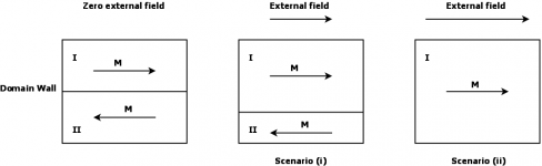
Let’s suppose, for simplicity, two adjacent magnetic domains (I) and (II) with opposed (anti-parallel) magnetization, and an external magnetic field in the easy axis, parallel to the magnetization of domain (I); then there are two different scenariosNo!! How many more times do I have to tell you that moving a domain wall involves flipping some spins, not flipping a domain?
i) The external magnetic field is strong enough to flip only some spins of domain (II)
By definition you have a new domain (I)+k(II), 0<k<1, we say that domain wall (I)/(II) has been moved.
ii) The external magnetic field is strong enough to flip all spins of domain (II)
Equivalently: The external magnetic field is strong enough to flip the magnetization of domain (II)
Equivalently: The external magnetic field is strong enough to flip the domain (II)
By definition you have a new domain (I)+(II), we say that domain wall (I) has been moved.
Conclusion: Moving a domain wall involves flipping some spins of a neighbor domain or flipping a neighbor domain.
Attachments
A PCI-6133 data acquisition system for the search coil analog input signal is likely to have been configured with at least 1Meg loading, and could be much more - but no details in any of the publications.
In comparison with any of the publications, or popilin's or the simple you tube test configurations, a typical output transformer would load any section of winding relatively heavily, and there may be cancellation of random BN signals from the winding configuration, and the winding self capacitance may shunt any BN signal, and there would be rejection of above-audio range noise ingressing somehow back in to the audio range, and there would be a S/N aspect for any amplified audio signal.
There are also those who have measured the noise floor of valve amplifiers using measurement bandwidths out to 90kHz using 192kHz soundcards, and the noise floor and full signal characteristics appear to show adequately low levels in the regions between test signals and their harmonics.
But, I can't wait for some aspiring hi-fi snake oil to claim some BN mitigation aspect of their amplifier design.
Last edited:
Well, there is the L.E.M. (Linearity Enhancement Module) by Custom Analogue (Joe Rasmussen) which injects HF bias into the amplifier front end to improve permeability at low signal levels (like used for tape recording).
Basically shaking up those magnetic domains so they don't have any coercive force or hysteresis to overcome (my words). Should prevent domain avalanching noise by removing the "friction".
Some info on their site (bottom of page):
Joe Rasmussen Pages
Seems an interesting idea. Whether it's actually needed, I'm not sure. Easy enough to try out. Apparently this technique was patented in the early 40's for tube amplifiers, but never caught on till lately. (easier to do now with a couple of IC's) (but was successful back then for tape recording electronics)
Menno van der Veen has some discussion here:
http://www.mennovanderveen.nl/nl/download/download_1.pdf
..
Last edited:
No problem YOU have BN noise, I don't! You have bad cores, I don't.Right now I finished my BN experiment, 60 pcs. GOSS 114mmx19mmx0.25mm, a transformer coil and a piece of (broken) magnet 10mm diameter x 1mm thick, connected to audio input of CRT TV, volume set at 30%, it exhibits BN, my guess is that my magnet is extremely small, but it works.
There thousands DIY'ers that use valve amps let's see how many have BN noise....
What about this to assign the right magnitude?
https://www.google.com.ar/url?sa=t&...sg=AFQjCNEjL6uQKLwtnXfPsZHGH2_1SqaH7A&cad=rja
That's ferrite. Do you use ferrite for audio transformers? Rubbish cores again.
I know that article. Why should I use that reference if there is a reference talking about the real thing? GOSS cores, good standard quality, have peak noise in the range of 1 mV. Not 100mV.
Didn't you post a video about last word? Ok I will leave you the last word and the pleasure to listen to BN noise. I listen to music!!!!!!😀
Have a good day. I have to work this weekend....
You do not have to wait so much. 😀But, I can't wait for some aspiring hi-fi snake oil to claim some BN mitigation aspect of their amplifier design.
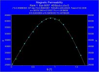
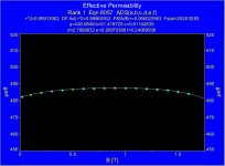
Magnetic permeability falls down either with frequency or with magnetic field, here a plot for a Japanese magnetic laminationSome info on their site (bottom of page):
Joe Rasmussen Pages
On the other hand, magnetic field also falls down with frequency
B(max) = [Vp(RMS) x 10⁸] / (√2 π S Np f)
BN increases with frequency, and also does hysteresis losses, then, in first approximation the “magical” device increases distortion and noise.
Another charlatan, equation 1-4 in his “paper” is wrong, as all his snake oil to sell expensive toroidal transformers.Menno van der Veen has some discussion here:
http://www.mennovanderveen.nl/nl/download/download_1.pdf
With the addition of an air gap, magnetic permeability falls down two orders of magnitude.
Contrary to Menno van der Veen claims, this is good because now magnetic permeability is quite constant all over the hysteresis loop regardless the frequency, this means a very thin hysteresis curve and hence more linearity, in good transformers this is a thin ellipse that is almost a straight line.
Hey, I use Italian GOSS lamination!No problem YOU have BN noise, I don't! You have bad cores, I don't.
No Pierpaolo, read again, ferrite is part of the set-up, the sample is NOSS.That's ferrite. Do you use ferrite for audio transformers? Rubbish cores again.
You overlooked the CERN paper, they need the highest quality magnetic material for their infernal machines, for both, iron-based and cobalt-based materials they measure BN of about 300mV at about 0.5TI know that article. Why should I use that reference if there is a reference talking about the real thing? GOSS cores, good standard quality, have peak noise in the range of 1 mV. Not 100mV.
Can we accuse them for wrong measurements?
Maybe they did not find the Higgs Boson after all. 😀
Have a happy weekend!Didn't you post a video about last word? Ok I will leave you the last word and the pleasure to listen to BN noise. I listen to music!!!!!!😀
Have a good day. I have to work this weekend....
Fushta! 😛😀
Attachments
Well, the HF bias scheme works good for tape recording. I think we all need to differentiate between domain flipping and domain avalanching. Avalanching is what is producing near audible effects. The magnetic material is like a pile of sand with "stiction" between granules. The HF bias shakes the pile so that it all flows more like water, preventing any buildup of cliff-hanger domains that will avalanche.
Putting an air gag (edit: ha-ha, I meant air gap!) into the magnetics to flatten permeability down is highly counterproductive. That just lowers the whole magnetics curve permeability by 100X, so everywhere is as bad as near the zero crossing. Magnetizing current becomes 100X bigger. That's just trading a minor problem for a major problem.
The tiny "noise" from individual domain flipping is unavoidable when the field changes (except maybe by severe low Z drive). I would be happy to have just THAT "problem", and avoid the REAL avalanching problem. Of course, low Z drive will fix avalanching too. So there is some question as to how necessary LEM type add-ons are with proper design (low Zout from the tube plates). (evaluations do seem to indicate LEM helps for typical designs, but typical is usually high Zo pentode) LEM probably makes the most sense for typical SE amplifiers with high Rp drive (no N Fdbk). But then SE OTs don't make any good sense either. (just use class A P-P with DC balancing current (high Z out) on one side, signal V on the other (low Z out), LEM optional)
..
Last edited:
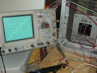
"I have the same scope!!"
I have the same curve as on the scope!
-----
ehhh, I don't see any integrator circuit there for taking the hysteresis curve? Might be why it's so flat lined.
..
I have the same curve as on the scope!
-----
ehhh, I don't see any integrator circuit there for taking the hysteresis curve? Might be why it's so flat lined.
..
Last edited:
Italian is not an assurance for quality. On top of that you need to find out how this as been treated and stored once out of the factory. Stress and other types of damage increase BN noise.Hey, I use Italian GOSS lamination!
NOSS is just as bad. The fact that it is SiFe alloy doesn't mean that it is comparabale to quality GOSS. The treatments and other processing make all the difference. I think that NOSS has not been used in output transformers for 60-70 years at least....No Pierpaolo, read again, ferrite is part of the set-up, the sample is NOSS.
Until now I can only see that standard good quality GOSS has 1 mV or so.
You overlooked the CERN paper, they need the highest quality magnetic material for their infernal machines, for both, iron-based and cobalt-based materials they measure BN of about 300mV at about 0.5T[/FONT]
Can we accuse them for wrong measurements?
Maybe they did not find the Higgs Boson after all. 😀
You can't compare audio with things that have nothing to do with it.
I can find you a diffraction spot from a crystal with an intensity just a tiny bit above the noise level (i.e. parasitic scattering due to air, slits and other stuff along the path of the X-ray beam). Something like the spot has 10 counts and the noise 7-8-9 counts on the detector. This happens every time in crystal structure determination from diffraction patterns at high resolution (i.e. atomic distance of the order of 1 Angstrom).
Last edited:
You can't compare audio with things that have nothing to do with it.
Amorphous and Nanocrystalline materials, puaj!!!
Fushta! 😛😀
- Status
- Not open for further replies.
- Home
- Amplifiers
- Tubes / Valves
- SE OPT Arcana