I think of it like water spigots. Unscrew or CCW to open the valve. 🙂
Directionally of rotation should not depend on orientation of PCB as long as looking at it from the top.
At certain balance conditions though CW will increase bias.
Directionally of rotation should not depend on orientation of PCB as long as looking at it from the top.
At certain balance conditions though CW will increase bias.
Hi Prasi,
I'm interested in one stereo HA board, I've added myself to the list:
xrk- 1 set (1 PSU+1 Stereo HA)
gannaji- 1 set (1 PSU+1 Stereo HA)
saheb- 1 set (1 PSU+1 Stereo HA)
kram- 1 set (1 PSU+1 Stereo HA)
btesize-1 set (1 PSU+1 Stereo HA)
rumina-1 set (1 PSU+1 Stereo HA)
nicusim-1 set (1 PSU+1 Stereo HA)
potepuh-1 set (1 PSU+1 Stereo HA)
e_fortier-2 PSU
touchdown -1 Stereo HA
Thanks
Nicola
With switching the input impedance R5 to 22k I am having a hard time getting the ability to set DC offset to zero and have the correct bias current of 100mA.
Hi Prasi,
Thanks for adding my name for the GB.
I have just calibrated 2 of the board and noticed that when orienting the board the right way, i.e. with the output transistors on the right side, you have to turn P1 and P2 counter clockwise to increase the bias, it's usually more intuitive to turn clockwise to increase bias. Maybe you could rewire P1, P2.
Just my 2 cents.
p.s. Worked right away. Thanks.
BR,
Eric
Hi Eric,
Great to hear that you had no problems to get your HA working.
what values of R5, R2/R3, R16/18/20 that you are using? the final design that i made uses R5=22k (w/o i/p coupling cap=jumper), R5=100k (with coupling cap=1uF, 5mm pitch), R2/R3=47R, R16/18/20=330R or single 1k res.
Thanks for your suggestion, one could just install the pots opposite to silk.
I did the design as per Juma's original suggestion to start with maximum resistance of pots for least bias and decrease the resistance to set the bias. http://www.diyaudio.com/forums/pass-labs/271926-f5-headamp.html#post4269989
reg
Prasi
Just wanted to some opinions regarding signal i/p connector that people prefer to use. the final design uses a 2.54mm pitch 2 pin header. i have tried possibility of jst / screw termi block, but seems difficult, as i had to accommodate 1uf coupling cap.
x, i know you prefer termi blocks😉...
x, i know you prefer termi blocks😉...
Attachments
Please allow for Molex KK 0.100 crimp connectors with same pin distance but with slightly wider footprint.
I like the Molex connectors too. The location at present would put it right against the amp front panel. I don't know how to bring it farther back away from panel to allow easier access when installing or removing plug from PCB. The PCB is now attached to front panel by virtue of pot soldered on. Getting the pot and heatsink holes for mosfets to line up may be tricky.
or a ribbon cable for those cases where the vol pot drill is on side of case...Should not be a problem. In extreme cases an extension shaft can be helpful.
care to share data sheet? Molex is a sea, not easily available in my place, except for look alikes and pc'sPlease allow for Molex KK 0.100 crimp connectors with same pin distance but with slightly wider footprint.
I might just be able to fit
http://www.molex.com/molex/products/datasheet.jsp?part=active/0022232021_PCB_HEADERS.xml
reg
Prasi
Last edited:
Hi Prasi,
I've added myself to the list:
xrk- 1 set (1 PSU+1 Stereo HA)
gannaji- 1 set (1 PSU+1 Stereo HA)
saheb- 1 set (1 PSU+1 Stereo HA)
kram- 1 set (1 PSU+1 Stereo HA)
btesize-1 set (1 PSU+1 Stereo HA)
rumina-1 set (1 PSU+1 Stereo HA)
nicusim-1 set (1 PSU+1 Stereo HA)
potepuh-1 set (1 PSU+1 Stereo HA)
e_fortier-2 PSU
touchdown -1 Stereo HA
albertNL- 1 set (1 PSU+1 Stereo HA)
Thanks
Albert
Hi Eric,
Great to hear that you had no problems to get your HA working.
what values of R5, R2/R3, R16/18/20 that you are using? the final design that i made uses R5=22k (w/o i/p coupling cap=jumper), R5=100k (with coupling cap=1uF, 5mm pitch), R2/R3=47R, R16/18/20=330R or single 1k res.
Thanks for your suggestion, one could just install the pots opposite to silk.
I did the design as per Juma's original suggestion to start with maximum resistance of pots for least bias and decrease the resistance to set the bias. http://www.diyaudio.com/forums/pass-labs/271926-f5-headamp.html#post4269989
reg
Prasi
Hi Prasi,
I only adjusted the bias at 150mA with 0mV DC offset, I did not yet installed an input cap (2.2uF) so I've no clue how it sounds. Working now on the PSU since the heatsinks seems a bit too small.
For the input connector, see what I've used, fits nicely and has screws. X will like 😉
http://www.digikey.com/product-detail/en/on-shore-technology-inc/OSTVN02A150/ED10561-ND/1588862
BR,
Eric
Attachments

Last edited:
Eric,
That's great that you got 0vdc offset and 150mA bias. What resistor values are you using? 68R or 47R? Nice minature terminal block with screws!
That's great that you got 0vdc offset and 150mA bias. What resistor values are you using? 68R or 47R? Nice minature terminal block with screws!
care to share data sheet? Molex is a sea, not easily available in my place, except for look alikes and pc's
I might just be able to fit
http://www.molex.com/molex/products/datasheet.jsp?part=active/0022232021_PCB_HEADERS.xml
reg
Prasi
i feel, its always good practice to get commonly held opinions/ user's opinions while designing the pcb's so that its easier for the people to build...
in any case, people could grab 2.54mm pin headers available in their nearest bin, or order molex part ...
one thing (or many things) to note here for the HA...(build notes!)
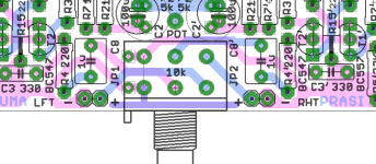
All resistors are 1/4 W, except, R13/17, should be 1W.
C5/C4, are 10mm dia electro caps, fit as big as possible (16v or 25 v parts),
C1/C2 have 2.5mm pitch x 7mm dia or 3.5mm pitch x8mm dia
P1/P2 are 3296W bourns 5k pots,
i/p coupling cap when used, is a good quality Epcos/Wima >=1uF 5mm pitch 63v film cap (with R5=100k) or jumper it and use R5=22k/10k even....
C3 (anywhere between 330p to 1n) is optional and should be a NPO/C0G type....
bypass caps (C6/7) should be 100nf , x7r ceramic smd with 1206 package and are purely optional.
T1/T2/T3/T4 could be BC547/557 as per silk or could be BC550/560 , pl match hfe using atleast multimeter...
i have had good experience in closely matching hfe of i/p pair on Apex Fx-8 (sweet), with 2-3mV DC offset...
, nothing is special to note here, the beauty being commonly available parts for this design.
reg
Prasi
Last edited:
Eric,Hi Prasi,
I only adjusted the bias at 150mA with 0mV DC offset, I did not yet installed an input cap (2.2uF) so I've no clue how it sounds. Working now on the PSU since the heatsinks seems a bit too small.
For the input connector, see what I've used, fits nicely and has screws. X will like 😉
OSTVN02A150 On Shore Technology Inc. | Connectors, Interconnects | DigiKey
BR,
Eric
you seem to have some very special parts in your stock... all resistors/pots/connectors+blue pcb.... wow! nicely done....i am drooling here....
do have a listen and share your views...
one thing, for R17/13, are you sure you used hefty resistors?
reg
Prasi
Last edited:
Thanks Prasi, everything is from Digikey
R13/R17 are really rated 1W but they are physically same as 1/4W, don't know why.
BR,
Eric
R13/R17 are really rated 1W but they are physically same as 1/4W, don't know why.
BR,
Eric
Eric,
That's great that you got 0vdc offset and 150mA bias. What resistor values are you using? 68R or 47R? Nice minature terminal block with screws!
I used 68 ohm.
- Home
- Amplifiers
- Pass Labs
- Juma's Head Amp