Let's mix it up somewhat and save those Toshiba JFETs, without comprimising SQ.
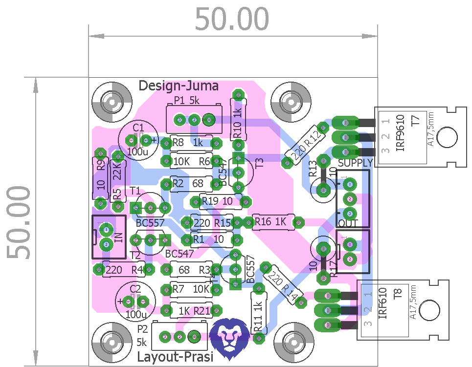
P1/P2 set the Iq of the output stage to about 50-100mA as well as DC offset at the output (start adjusting with maximum resistance of the pots).
As someone made a PCB for that one ? (see post no.2 of this thread)
I like what Juma says about saving those Toshiba JFETs, without comprimising SQ 🙂
BR,
Eric

Prasi,
The scale is hard to tell how small it is - but best way is to imagine 35mm film, it's about same as one frame including the perforated transport edges. Maybe I will take a photo wit it in my hand.
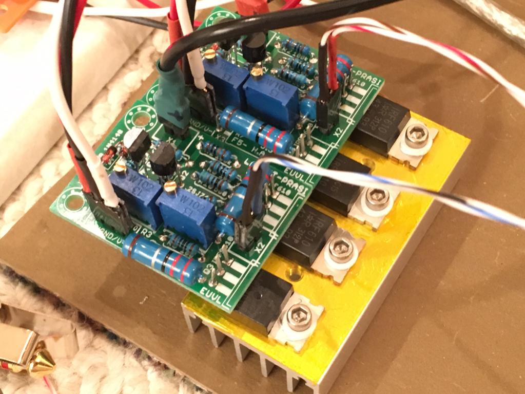
Anyhow, your layout has now been verified to be perfectly excellent. It's playing right now as I type into some test headphones. Very quiet - no hiss or hum with the music turned off. Cannot tell it is powered on. I had to build a PSU for it which is why the testing took so long. A CRCRC with 2200uF//0.47R//2200uF//0.47R//2200uF followed by a LM7x15 regulator per rail. I would have made a Juma cap multiplier but don't have enough IRF610/9610's MOSFETs to make them with. The setup was very easy - with trimpots in centered stock position, it powered up at 200mA bias. I am using 2.2R Drain resistors so I adjusted for 0.22v across 2.2R while monitoring second DVM on output to adjust DC offset. Range is really smooth and precise. DC offset drifts a bit due to inputs out in air, maybe +/-7mV.
One thing I really like with this layout is that the two pots are next to each other. Believe it or not, that makes a difference when trying to adjust both bias and offset at same time. Verry easy and quick compared to two pots separated on each side of board.
The sound is excellent as expected. I have it mounted on an undersized heatsink for testing purposes (using fan). For regular amp, a heatsink this size is good for one channel, not two.
Anyhow, easy build, layout is guaranteed to work with no fuss.
Thanks for making the layout - this will allow me to fit it into a very small box.
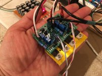
Here is the stereo amp (two channels) in my hand for size:

The scale is hard to tell how small it is - but best way is to imagine 35mm film, it's about same as one frame including the perforated transport edges. Maybe I will take a photo wit it in my hand.
Anyhow, your layout has now been verified to be perfectly excellent. It's playing right now as I type into some test headphones. Very quiet - no hiss or hum with the music turned off. Cannot tell it is powered on. I had to build a PSU for it which is why the testing took so long. A CRCRC with 2200uF//0.47R//2200uF//0.47R//2200uF followed by a LM7x15 regulator per rail. I would have made a Juma cap multiplier but don't have enough IRF610/9610's MOSFETs to make them with. The setup was very easy - with trimpots in centered stock position, it powered up at 200mA bias. I am using 2.2R Drain resistors so I adjusted for 0.22v across 2.2R while monitoring second DVM on output to adjust DC offset. Range is really smooth and precise. DC offset drifts a bit due to inputs out in air, maybe +/-7mV.
One thing I really like with this layout is that the two pots are next to each other. Believe it or not, that makes a difference when trying to adjust both bias and offset at same time. Verry easy and quick compared to two pots separated on each side of board.
The sound is excellent as expected. I have it mounted on an undersized heatsink for testing purposes (using fan). For regular amp, a heatsink this size is good for one channel, not two.
Anyhow, easy build, layout is guaranteed to work with no fuss.
Thanks for making the layout - this will allow me to fit it into a very small box.
Here is the stereo amp (two channels) in my hand for size:
Attachments


Last edited:
Prasi,
The scale is hard to tell how small it is - but best way is to imagine 35mm film, it's about same as one frame including the perforated transport edges. Maybe I will take a photo wit it in my hand.
Anyhow, your layout has now been verified to be perfectly excellent. It's playing right now as I type into some test headphones. Very quiet - no hiss or hum with the music turned off. Cannot tell it is powered on. I had to build a PSU for it which is why the testing took so long. A CRCRC with 2200uF//0.47R//2200uF//0.47R//2200uF followed by a LM7x15 regulator per rail. I would have made a Juma cap multiplier but don't have enough IRF610/9610's MOSFETs to make them with. The setup was very easy - with trimpots in centered stock position, it powered up at 200mA bias. I am using 2.2R Drain resistors so I adjusted for 0.22v across 2.2R while monitoring second DVM on output to adjust DC offset. Range is really smooth and precise. DC offset drifts a bit due to inputs out in air, maybe +/-7mV.
One thing I really like with this layout is that the two pots are next to each other. Believe it or not, that makes a difference when trying to adjust both bias and offset at same time. Verry easy and quick compared to two pots separated on each side of board.
The sound is excellent as expected. I have it mounted on an undersized heatsink for testing purposes (using fan). For regular amp, a heatsink this size is good for one channel, not two.
Anyhow, easy build, layout is guaranteed to work with no fuss.
Thanks for making the layout - this will allow me to fit it into a very small box.
Here is the stereo amp (two channels) in my hand for size:
Wow! thats very small, nice work with set-up. Happy to see you happy with my layout work.
reg
Prasi
It's sounds very good and a pleasure to build. Unfortunately, it's packed up and on its way to its new owner. 🙂
As someone made a PCB for that one ? (see post no.2 of this thread)
I like what Juma says about saving those Toshiba JFETs, without comprimising SQ 🙂
BR,
Eric
123-juma.... an hour's job!, very very draft and no thought!! seperate thread if needed! 😉
reg
prasi
Attachments
Last edited:
Prasi,
Nice! Looks like I need to place another order on Seeedstudio 🙂 50mm boards are on sale for $6 for 10. I think new thread would be good. I am curious what this sounds like. Although these are BC647/567 we know BC550/560 combos are very low noise high performance BJT transistors. They are the basis of Dadod's gainwire (maybe 30 of them).
Nice! Looks like I need to place another order on Seeedstudio 🙂 50mm boards are on sale for $6 for 10. I think new thread would be good. I am curious what this sounds like. Although these are BC647/567 we know BC550/560 combos are very low noise high performance BJT transistors. They are the basis of Dadod's gainwire (maybe 30 of them).
Last edited:
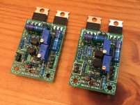
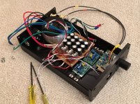
As I gave my first set away, I just built another set last night. Looks just like the first set:
Fired it up and adjusted to 100mA bias easily enough. Now making the cross feed filter and stereo volume knob. Will fit it all in an aluminum Breeze audio head amp case. No fins but main shell body panel should be sufficient heatsink.
1506 E3 Full aluminum headphone amplifier enclosure / case /preamp chassis-in Amplifier from Consumer Electronics on Aliexpress.com | Alibaba Group
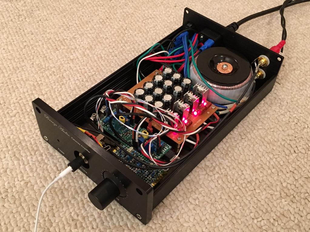
Fit check
It looks like everything will fit just fine. This case is really well made and everything fits together quite well. Great value at $40 including shipping.
That is an Antek model 0215 (25VA) toroid, so should be plenty of power.

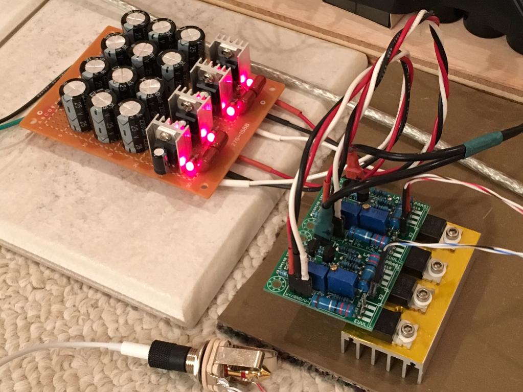
Closeup of cross-feed filter and amp boards. The volume pot is velvety smooth and noise-free.

It looks like everything will fit just fine. This case is really well made and everything fits together quite well. Great value at $40 including shipping.
That is an Antek model 0215 (25VA) toroid, so should be plenty of power.
Closeup of cross-feed filter and amp boards. The volume pot is velvety smooth and noise-free.
Attachments

Last edited:
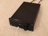
All Buttoned Up
The amp is now completed, all buttoned up and working. Just need to add an LED power on indicator for the front panel. Sounds great - absolutely silent with no music playing. Case doesn't even get warm - the surface area dissipates the heat just fine - no fins needed.

The amp is now completed, all buttoned up and working. Just need to add an LED power on indicator for the front panel. Sounds great - absolutely silent with no music playing. Case doesn't even get warm - the surface area dissipates the heat just fine - no fins needed.
Attachments

single wires all over !
Some coaxial with big loops at the terminations !
What about pairing up the Flow and Return of each connection?
Then twist each pair to minimise interference.
Some coaxial with big loops at the terminations !
What about pairing up the Flow and Return of each connection?
Then twist each pair to minimise interference.
single wires all over !
Some coaxial with big loops at the terminations !
What about pairing up the Flow and Return of each connection?
Then twist each pair to minimise interference.
Only single wires on mains from IEC to trafo and trafo to PSU bridge. All others are twisted or coaxial. I don't have any interference pickup or hum/hiss/noise issues. This amp is dead silent.
I don't believe you.
That's unfair. My latest amplifier design is all new because I went to great lengths to minimize hum and noise. Sure, I twist the wires and all that, but the twisting isn't the most important part. I have many single wires, and a transformer just about on top of the amplifier boards, right next to long single wires connecting the power transistors, and the amp is absolutely dead silent. You cannot hear hiss or hum whatsoever.
I have a friend who is extremely finicky when it comes to his sound. I built his amp, and the hum is minimal, but he can't live with it. I'm busy sorting the hum out, and in the meantime, I've lent him my new amp - he says it's dead silent. As in, the only way you know the amp is on is when you put something into the input. You even doubt the power LED.
I don't believe you.
What don't you believe? That I twisted the wires as I said or that it's dead silent? I built an earlier veroboard version of this amp using a cardboard box with no attention to twisting wires and it is also dead silent. Maybe some luck involved as I have experienced other times where hum pickup is an issue. I think the most important thing is star ground to avoid ground loops internal to the amp and PSU. The cardboard amp is also dead silent, as in, you cannot know it's on until you play music and same as mrcloc, the LED is an oddly unbelievable indicator.
I am pretty finicky with hum/hiss as well and this amp is fantastic.
Last edited:
Moved form the pics Thread
I can see a couple of coaxial cables. There are maybe many more but since they are black it's difficult to pick them all out.
I can see a couple of coaxial terminations. The loop area at those terminations is big. They can usefully be made very much smaller.
There are numerous coloured wires that ate not coaxial. To me they look like single wires.
Look at the top left next to the side panel Starting from there and moving towards the big black transformer retaining plate:
I see
grn - blk - wht - red - red - grn - red - blu - grn- grn washer plate. That at least 10 single wires that are not close coupled as PAIRS. None of them are twisted.
grn - blk - wht - red - red - grn - red - blu - grn- grn washer plate. That at least 10 single wires that are not close coupled as PAIRS. None of them are twisted.
Those are the wires from mains to trafo input (red and black - two pairs since running parallels inputs for 120vac) and AC out (blue and green). No I did not twist those but they are all bundled up in one corner where mains entry is. The AC output of the trafo is 4 wires, two connected for center tap. Should those three effective wires be twisted? It's all connected with bullet or spade connectors so twisting is possible but wires are kind of nice where they sit and twisting would add bulk.
What does the Hum+Noise measure?
If you were to use that as the cable driving stage into a power amplifier, what would the H+N at the pre-amp output give as a H+N at the power Amplifier output after applying a gain of ~+28dB?
If you were to use that as the cable driving stage into a power amplifier, what would the H+N at the pre-amp output give as a H+N at the power Amplifier output after applying a gain of ~+28dB?
What tool would be needed to measure the noise and hum? All I have is a DMM with AC volts. The headphone listening test says it's silent so I would expect the output to register less than 1mV on the AC volts.
- Home
- Amplifiers
- Pass Labs
- F5 Headamp ?