thinking to diy planar magnetic midrange any idea what material is used in
BG Neo I think some composite material
Magnepan I read somewhere as Mylar but which on in precise?
BG Neo I think some composite material
Magnepan I read somewhere as Mylar but which on in precise?
magnepan used 12 micron, but you could use 6 as well. i can imagine the neo uses kapton.
Mylar is easy to find from 3 to 30 micron or even thicker. look for RC airplane shops or on ebay 20 meter rolls very cheap. kapton is hard to find mostly they are tapes and are a bit on the thicker side. i got a roll of 200mm wide somewhere.
The biggest problem is that neo uses traces in the form of foil etched from the kapton, a kapton laminate with the proper thickness alu and lowest thickness kapton is very very hard to find. i've not yet see any one get it. even a mylar laminate is very hard to get. i bought some mylar alu laminate from i think bandsei, but he also only had a sample from the factory we should order in the range of kilometers before they are interested.
i would be interested in kapton/alu also every few weeks someone asks for this stuff so.
kapton/alu is the only product i did not manage to get in 12 years of doing this stuff and i made allot of weird speakers with weird components. 🙁
magnepan uses aluminum wires and or aluminum foil. something you could do with aluminum tape as well.
you can get small width tape from the maskingshop.co.uk
Last edited:
i got some laminate coming my way. after all that time... not sure yet if usefull... i do hope so money wise 🙂
its a 9 micron alu on 12 micron polyesther i will report back later on, when i received the stuff else i have packing paper for presents for my whole life to come !
its a 9 micron alu on 12 micron polyesther i will report back later on, when i received the stuff else i have packing paper for presents for my whole life to come !
BG Neo uses an aluminium/Kaladex laminate. In some writings polyimid is mentioned. In another aluminium/Teonex laminate. At least it is all DuPont. Magnepan use Mylar 12 µm and in a few midrange drivers 6 µm. Most common laminate is 9 µm aluminium/12 µm Mylar/2 µm adhesive. Kapton is sometimes criticized for being "noisy".
BG Neo uses an aluminium/Kaladex laminate. In some writings polyimid is mentioned. In another aluminium/Teonex laminate. At least it is all DuPont. Magnepan use Mylar 12 µm and in a few midrange drivers 6 µm. Most common laminate is 9 µm aluminium/12 µm Mylar/2 µm adhesive. Kapton is sometimes criticized for being "noisy".
nice info. i finally got my hands on the last 9AL/12 polyesther/2 adhesive. i hope to receive it at the end of next week or the week following.
we will see how well it works, certainly enough to do some tests 😉
of course, it is kind of the reason why i finally took the change and get a roll since i know that there is demand , there has been the last 8 years as far as i know. and with this knoledge i wanted to take the change this time. the same goes for rubber magnet if you are interested? i wanted to let them produce 4mmx3.2 strips of ferite rubber magnet something like magnepan. these are not strong at all but the trick is to use many. depending on buying a few meters or want to share one batch prices vary. i once had a big strip of there material and cut it to size and made a tweeter, http://www.diyaudio.com/forums/plan...t-poor-mans-magneplanar-tweeters-revisit.html
but having them slit it to the right size is beter ofcourse 🙂 for width i used the width of the smal magnets in magnepans (tweeter section) bcause with these magnets you can made tweeter sections as wel as bass sections. with the bass magnets you cant do the opposite since the ratio conducter vs foil will be to low and it will sound honky, only problem i can think of is that field strength with a bigger DC spacing for bass could be a problem, i did not test this yet. but if there is enough animo i could let them make wider strips for bass purposses to 9 mm for instance
the very best best would be going neo's ofcourse ,but it is again hard to find an suitable neo's that are not that expensive. they need to be long and thin. like in the neo's for instance. but for a bass panel that is going to be rather expensive.
Raidho i cant seem to see how this oen is build up ? normal ribbon or planar ? resonance free is assume ribbon , so allot of traces on the foil then get it trough a corrugation tools i guess. not sure if the foil will hold shape. well we can try for sure 🙂
Last edited:
Sorry if this strays from the topic - hope not...
How does this work really. Anyone can guess? Magnet configuration?
https://dl.dropboxusercontent.com/u...Handmade042013/Raidho-Handmade-tweeter-10.jpg
//
How does this work really. Anyone can guess? Magnet configuration?
https://dl.dropboxusercontent.com/u...Handmade042013/Raidho-Handmade-tweeter-10.jpg
//
that would be weird in a ribbon config, the current should all go down or all up. and some how getting feed back in on the other side. there membrane looks weird,
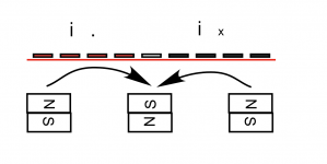
i think there are 3 magnets, facing you north-south-north. so under the foil is one more magnet, thats the only thing i can imagine that works.
i think there are 3 magnets, facing you north-south-north. so under the foil is one more magnet, thats the only thing i can imagine that works.
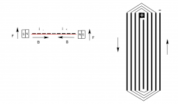
What you say make sense. I have never really dwelled into how these work. What do you make out of the picture in the link in post #8? If I follow the traces they seem to go around which would indicate that the the current would indeed go in one direction on one side of the membrane and in opposite direction on the other side. The middle conductor, that seem to start at the bottom of the picture don't seem to be connected - it ends in the top. The big white pad in the top seem to be the start - the end is covered by the hand? I assume that what looks white, is alu.
//
//
Last edited:
Its a standard arraingment. 3 Rows of magnet , NSN , under a flat "coil" .
The kapton VS polyester film thing is interesting in that once you laminate with a mushy viscous adhesive and some foil the "sound" of eather one is largley swamped out in a structure like a ribbon or a planer. On their own I suspect Kapton is a bit better damped than mylar.
Laminating is done with a "roll coating" process and the thinner materials that make a good speaker are rare. The ones that can do it ?? want a big $ minimum order.
I have experamented with a wide range of foil/adhesive/backing thicknesses, making woofers, mids and tweeters. In all of them reguardless of overall mass, ones where foil was thicker than the backing were the best performing.
For planer mid I like, foil .7 mill , adhesive .3 mill , backing ( mylar or Kap) .3 mill. IMO thicker adhesive or backing starts to suck the life out of the sound.
Ive made ones with thinner foil etc and the very lowmass designs have their strengths BUT, IMO they dont have the dynamics and the overall balance that the heavyer foiled ones have when everything is right with proportions of adhesive and backing.
Yes thats it
the wiggly looking traces are the interesting detail. There may be some improvment in resonant activity at some freqs but I would be suprised if a big difference. May also be some loss of sensativity with such an arraingment
Apogee worked a similar wiggly trace design at some point in their Mid ribbons. Ive tryed that one myself and compared to straight trace but wasnt convinced there was any improvment in sound.
Last edited:
Thanks!
Reason for wiggily traces:
- wanted more mass
- wanted higher impedance (hmm, better ways exists)
- wanted more tension to get it uniform in x and y dir.
all of above in a certain combination.
lowmass, you seem to sit an a lot of experience. Would be very interesting to see some pictures/measurements/anecdotes from your ventures. Your info in post #14 is already very useful - thanks you for that!
//
wiggle tracer also make a higher drive area without getting impedance down.
@lowmass you do thin stubstrates in mil 🙂 when calculated back
Foil 17 micron adhesive in 7 micron (why so much adhesive) mylar also around 7.
i have a hard time getting 7 or 6 pre laminated , i get 9AL 12 polyesther and samples of 12/12 and 25/12 soon. really looking forward to play 🙂
@lowmass you do thin stubstrates in mil 🙂 when calculated back
Foil 17 micron adhesive in 7 micron (why so much adhesive) mylar also around 7.
i have a hard time getting 7 or 6 pre laminated , i get 9AL 12 polyesther and samples of 12/12 and 25/12 soon. really looking forward to play 🙂
I suppose full drive only appear when trace is 90 dwg to B
thats true, but i recon the length of extra coil you can cramp in goes up, and my guess would be that the netto win of having the coil sligtly under an angle 45 degrees will still gain enough. and the reason for not doing it in straight lines could be tolerances with etching or something.
but you are right about that it forces the membrane slightly off the direction you would want it to be, one thing is because it zigzags one crinkly will push it to front and slightly down, and the next crinkle to front and up. but because it cant move up and down i can imagine you still have a gain in output and movement to the front.
allot of guessing 🙂
i will try this for sure to see what happens on a simple motor, then etch 2 membranes. it is a way of increasing power handling for intance
Last edited:
WrineX, I hear ya about "play". Discovery is best part of this 😉
Yes getting anything below about 12 micron in common laminate will likley be impossible unless U find a roll coater that just happens to have some left over from a custom run.
Y so much adhesive? Well theirs much to say there. I look at laminated ribbon/ plainer same as trying to damp any thin rigid material. For example take car body panel damping methods or speaker box panel damping. A layer of material is applied that has hysteric property. This tends to lower the main resonance a bit BUT more importantly it changes the mechanical property of the panel in a way that can suppress higher frequency resonances. This is where its most effective.
The issue with this method is to get a good "impedance match" without adding so much mass that you have killed sensitivity and or dyed up the sound. The " impedance match" is basically matching the mass of the adhesive/ backing combo to the foil mass to get a good energy transfer from the foil to the adhesive/backing. Think of it like this... try hitting a baseball with a light weight wiffle ball bat. Then hit that same ball with a real baseball bat. Much better energy transfer as the mass of the two is better matched.
So a certain amount of adhesive and backing mass can be a good thing, BUT its far from exact science and must be finessed to find the sweet spot. In the end trial and error hard work and hrs of listening is necessary to nail down a good combination.
What I shoot for is to get as much of that lively and exciting quality that FO (foil only) ribbons have without the metalic edgy signature.
TNT,
ive spent the last 20 yrs attempting to develop a small true ribbon that can operate down to 500 hz. We have seen small tweeter ribbons for years BUT they are typically limited to going no lower than about 1.5Khz and for the majority of the larger woofers out there you really need to cross over at about 500 hz to get that midrange magic we are looking for. The problem is there are very strong standing wave activity in typical ribbon structures below 1.5K and it simply cannot be damped well with standard ribbon designs. To get around this problem ribbon makers just typically make large long ribbons.
A few years back I made a discovery that allows a 6 inch long ribbon to operate reliably down to 500 hz with only a 2nd order xover filter. I applied for a patent, and started my own company. For this reason I dont post too many pics😉. However I have a soft spot for the DIY community so I give info like above from time to time.
The planers like the BGs are an answer to getting a low crossover point in a smallish package BUT IMO there is still two issues. 1-their wide so horizontal dispersion is a problem requiring a separate tweeter. 2- IMO as good as the planer is I think the ribbon is still a bit higher class sonic once the lower freq resonances are controlled..
- Status
- Not open for further replies.
- Home
- Loudspeakers
- Planars & Exotics
- BG Neo and Magnepan Diaphragm material