I made some guitar preamps and measure the output with a multimeter to figure out the output voltage. I play an E or A chord and strum vigorously. I simultaneously measure the output with a multimeter. Is this a valid way to get the output of the preamp? I have measured with an old needle type ac voltmeter and digital voltmeter and they both tend to agree. As I understand it, the guitar puts out different voltages for different frequencies and has a different output impedance for different frequencies. I am running the preamp into a power amp which is supposed to accept about 1 v rms and I'm not sure if this is a valid way to measure. What is the best way to figure out the output voltage of the preamp? I have modelled the preamps in LTspice and used .18v amplitude and 1khz with 10k output impedance and this seems to roughly agree with what I'm measuring on the multimeter.
Last edited:
As a crude measure, that ought to work. After all, in guitar amps, the difference between 0.8v signal and 1v signal is not all that important. Turn the volume control up or down a little to compensate.
The problem with meters is that they respond to different frequencies. The "true RMS" ones will probably track your audio better. But regular ones will work up to maybe 1kHz, at least the ones I have had over the years. over that, the response falls off. In my shop, just to fight ear fatigue, I mainly use 100Hz, until some specific need arises for higher freqs. MY meters all seem to handle 100Hz with ease.
Have you a scope in reasonable calibration? Watching a waveform on that will probably be more accurate over the freq range.
Using oscilloscope
Thank you for your response. I have a small oscilloscope i can make work. When you say use the oscilloscope do you mean use a sine wave generator and watch the response over the frequency spectrum. Or are you saying watch the composite signal of the guitar on the oscilloscope. Of course it wont trigger but you would be able to gauge roughly the peak voltage values
Thank you for your response. I have a small oscilloscope i can make work. When you say use the oscilloscope do you mean use a sine wave generator and watch the response over the frequency spectrum. Or are you saying watch the composite signal of the guitar on the oscilloscope. Of course it wont trigger but you would be able to gauge roughly the peak voltage values
Or are you saying watch the composite signal of the guitar on the oscilloscope.
Of course it wont trigger but you would be able to gauge roughly the peak voltage values
That's right. If you get around 1.5V peak voltage, that should fully drive the 1Vrms amp.
Last edited:
Sometimes to can pick up a older true rms meter, rack mount, on Ebay for cheap. I got a Racal wideband level meter and it has a peak and hold function, just strum real hard and it saves the highest level, good for comparing pickup outputs.
It depends what you are trying to measure. If you are trying to measure the output under normal operating conditions, definitely strum a guitar and use a scope or true rms meter to measure the average level. Just be aware that this value could be drastically different with a passive guitar vs an active guitar.
However, if you want to measure the clean headroom or frequency response, you might want to use a sine wave generator on the input and measure the output with a scope
However, if you want to measure the clean headroom or frequency response, you might want to use a sine wave generator on the input and measure the output with a scope
A 1kHz meter bandwidth may be enough for this particular application. A 21-fret electric guitar has no fundamental notes above 1108.73 Hz; a 22-fret one only gets to 1174.66 Hz....regular ones will work up to maybe 1kHz...over that, the response falls off.
I know there are harmonics above that, but probably most of the energy is in the lower frequencies, as usual with music.
-Gnobuddy
Agree with above posts, and add.
With a regular meter set to AC voltage you measure the "average" value of your signal, fine to set up the sensitivity of your preamp or power amp.
In fact you set it to be at least 2x or 3x as sensitive, so you don´t *need* to set the volume pot to 10 all the time to get full volume, you always need some extra gain under the hood so in the very common case of having weaker pickups, weak strummer or, say, poor cables or pedals, you can still have some gain reserve on tap .
Classic "unwritten rule" in many guitar amps, started by none less than Leo Fender long long ago was to set system sensitivity so amp is full power (on the edge of clipping) when set around 6 or 7 on a log pot scale.
Now if you want to know about possible clipping, you need to know peak to peak voltage, because preamp or amp signal must swing between power rails but not surpass them.
Scopes are perfect for that, modern meters do not show peak to peak voltage (old vacuum tube ones did) but you can easiy build a peak to peak probe and measure the resulting DC voltage with any meter:
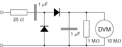
You need Germanium diodes for this (still available) or worst case Schottky diodes; plain Silicon will chop off too much, specially at low values.
With a regular meter set to AC voltage you measure the "average" value of your signal, fine to set up the sensitivity of your preamp or power amp.
In fact you set it to be at least 2x or 3x as sensitive, so you don´t *need* to set the volume pot to 10 all the time to get full volume, you always need some extra gain under the hood so in the very common case of having weaker pickups, weak strummer or, say, poor cables or pedals, you can still have some gain reserve on tap .
Classic "unwritten rule" in many guitar amps, started by none less than Leo Fender long long ago was to set system sensitivity so amp is full power (on the edge of clipping) when set around 6 or 7 on a log pot scale.
Now if you want to know about possible clipping, you need to know peak to peak voltage, because preamp or amp signal must swing between power rails but not surpass them.
Scopes are perfect for that, modern meters do not show peak to peak voltage (old vacuum tube ones did) but you can easiy build a peak to peak probe and measure the resulting DC voltage with any meter:
You need Germanium diodes for this (still available) or worst case Schottky diodes; plain Silicon will chop off too much, specially at low values.
Thank you, question about circuit.
Thank you so much for the info. Mitchmev, I was trying to measure the output under normal operating conditions (I think in my circuit I may add soft clipping to limit the active pickup signal). JMFahey, that is a very cool circuit. If I understand it, that is more or less rectifying the signal and charging the capacitor to peak value, like a simple power supply (transformer+rectifier+capacitors). I have 1n34as (measure .3v forward voltage drop) from china and 1n5819/1n5819's (measure .2v forward voltage drop) and I will build soon. I would think taking peak measurement and multiplying by .707 ought to be close enough for my purposes to get close to rms. One question though, say I use a 1n34a diode with .3v forward voltage drop, do I need to add .3v to my measured value to compensate for the forward voltage drop of the diode?
Thank you so much for the info. Mitchmev, I was trying to measure the output under normal operating conditions (I think in my circuit I may add soft clipping to limit the active pickup signal). JMFahey, that is a very cool circuit. If I understand it, that is more or less rectifying the signal and charging the capacitor to peak value, like a simple power supply (transformer+rectifier+capacitors). I have 1n34as (measure .3v forward voltage drop) from china and 1n5819/1n5819's (measure .2v forward voltage drop) and I will build soon. I would think taking peak measurement and multiplying by .707 ought to be close enough for my purposes to get close to rms. One question though, say I use a 1n34a diode with .3v forward voltage drop, do I need to add .3v to my measured value to compensate for the forward voltage drop of the diode?
If you're measuring a fairly large voltage (several volts), the diode drop can usually be ignored.do I need to add .3v to my measured value to compensate for the forward voltage drop of the diode?
If you're measuring a fairly small voltage (under 1V), the diode drop is significant - and it's not exactly a constant, the diode voltage drop is proportional to the logarithm of the current flow through it, so it does vary a little with applied voltage.
If you have access to a sine-wave generator, you might be able to use a second DMM to calibrate the home-brew meter; just use a low enough AC frequency to stay within the (2nd) DMM's bandwidth.
BTW, the circuit Fahey posted is a voltage doubler...so you'll need more than a factor of 0.707 to correct for it!
So: set the AC frequency low enough to trust the 2nd DMM's AC voltage measurement. With the frequency fixed, vary the voltage from the sine-wave generator, read the correct value from the 2nd DMM, and note the corresponding reading on the DMM connected to the diode rectifier/doubler circuit.
If you make a little table of values read from both meters, you can use it to correct for the diode drop.
With the calibration table in hand, you can now use Fahey's circuit to measure frequencies which are too high to trust the DMM's AC measurement capabilities.
This may be overkill for your purposes, though, unless you need a pretty accurate measurement...
-Gnobuddy
Thank you, I will calibrate the circuit like suggested
Thank you I was wondering about the extra diode, it did remind me of the Greinacher voltage doubler circuit I looked up a while back. Anyhow, I see what you mean. It should be very easy to calibrate the circuit as you described. From my laptop I will go to youtube and find a 100hz signal and use this as a signal generator and adjust the output volume oon the laptop. I will measure the voltage on DMM, write down the value, then hook the laptop up to the circuit and measure the DC measurement from the home brew meter. I'll then adjust the volume on the laptop and take several points this way. I think that should work fine. I'll also publish my results when I'm done, in case anyone else wants to use the circuit. I'll use some schottky diodes 1n5819s or 1n5818s because the voltage drop is lower, and my 1n34as I bought off ebay are a little suspect and I hear those diodes tend to be somewhat variable anyhow. I'm thinking the schottky diodes may have more uniform characteristics if someone is to build this. Thanks again, I will post my results!
Thank you I was wondering about the extra diode, it did remind me of the Greinacher voltage doubler circuit I looked up a while back. Anyhow, I see what you mean. It should be very easy to calibrate the circuit as you described. From my laptop I will go to youtube and find a 100hz signal and use this as a signal generator and adjust the output volume oon the laptop. I will measure the voltage on DMM, write down the value, then hook the laptop up to the circuit and measure the DC measurement from the home brew meter. I'll then adjust the volume on the laptop and take several points this way. I think that should work fine. I'll also publish my results when I'm done, in case anyone else wants to use the circuit. I'll use some schottky diodes 1n5819s or 1n5818s because the voltage drop is lower, and my 1n34as I bought off ebay are a little suspect and I hear those diodes tend to be somewhat variable anyhow. I'm thinking the schottky diodes may have more uniform characteristics if someone is to build this. Thanks again, I will post my results!
Last edited:
Built and tested at 100hz, how high of frequencies will this circuit measure?
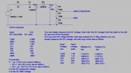
Ok thanks everyone. I built the circuit and also simulated. The simulation doesn't seem to work well at all. Anyhow, I used a 100hz sine wave at various voltages from 60mv to 1v. I then fit the 3 curves V=mx, V=mx+b and V=cx^2+ mx+b, the lower the voltage goes, the more complicated a formula you need. In the case of the simplest formula, which is ac voltage = .4xDC voltage measured, I just used a voltage divider with 2 taps, so you don't have to fool with the formulas or tables above 200mv. I just used E12 series values to get something close enough. You could use trimpots if you wanted to be more accurate.
I did all this using a 100hz signal (not sure how high the DMM measures). I'm assuming it would measure higher frequencies in a similar fashion?
Attachments

changed charging capacitor to 10uf instead of 1uf
I tested this with a clean guitar signal on my preamp, the reading on the DMM still jumped around a little too much, so I replaced the charging capacitor with a 10uf capacitor instead of a 1uf capacitor and this seemed to work a little better, but you have to wait for the capacitor to discharge a second or so if you make any adjustments and re-measure. I've posted the corrected circuit here. Thanks everyone.
I tested this with a clean guitar signal on my preamp, the reading on the DMM still jumped around a little too much, so I replaced the charging capacitor with a 10uf capacitor instead of a 1uf capacitor and this seemed to work a little better, but you have to wait for the capacitor to discharge a second or so if you make any adjustments and re-measure. I've posted the corrected circuit here. Thanks everyone.
Attachments
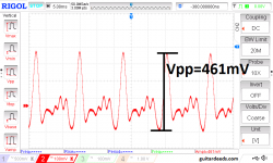
Yeah, unfortunately the guitar signal itself consists of a very strong, and very brief, initial transient (usually only a few milliseconds long), followed by a fairly rapid decay (that only lasts a few seconds at most).I tested this with a clean guitar signal on my preamp, the reading on the DMM still jumped around a little too much
This is a tough signal to measure with any sort of digital meter! There are some types of measurements where an old-fashioned analog meter, or a bar-graph type of meter, is a bit better suited than a "proper" digital meter. Your eye can follow a pointer (or bar-graph) even though it's changing fairly rapidly. But a rapidly changing digital display is totally unreadable.
Even an old-fashioned analog 'scope isn't very well suited to measuring this, unless it's a storage 'scope. A modern digital scope, though, can do a pretty good job.
The bigger capacitor will also probably eliminate that initial transient voltage, so what you read will be some sort of heavily averaged voltage. (That isn't necessarily bad, you did the right thing to make the DMM readable - just keep in mind that big initial peak voltage probably isn't going to show up in your measurement.I replaced the charging capacitor with a 10uf capacitor instead of a 1uf capacitor and this seemed to work a little better, but you have to wait for the capacitor to discharge a second or so if you make any adjustments and re-measure.
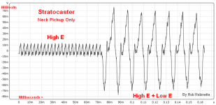
A while ago I had the same question (how big is a raw guitar signal?), and I found a couple of oscilloscope screen captures online; I'll attach them in case you find them helpful.
Incidentally, neither of these images shows an initial transient; the second image was probably taken well after the initial pick attack, but I'm confused about the first (the one that shows both high E and low E output). Why doesn't this include a transient at the point where the low E string was picked? 😕
-Gnobuddy
Attachments
One more thing to try: a long time ago, I saw a circuit which used the base-emitter voltage of a PNP transistor to compensate (more or less) for the voltage drop in a rectifier diode. Acting together, they formed an improved low-voltage rectifier diode.
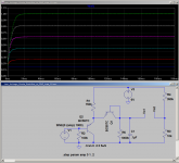
I ran with that idea a bit; why not use a second identical (more or less!) PNP transistor, diode-connected, so as to do a better job of matching the offset voltages?
The result is attached. I don't know how much we can trust LTSpice with a simulation like this one, but it looks like the roughly 600 mV - 700 mV threshold voltage of a silicon diode is reduced to somewhere under 200 mV using this approach.
In the figure, Q1 is acting as a diode (base shorted to collector). Q2's job is to provide the DC voltage offset that compensates for Q1's turn-on voltage.
As shown, the input impedance is only around 10k; insufficient for a normal guitar pickup. Perhaps a buffer to feed the rectifier?
The other thing to keep in mind is the gradually escalating complexity here - we've gone from simple RMS meter to active circuits with a power supply and a couple of transistors. If you're going that far, perhaps go all the way to an op-amp based precision rectifier circuit. I don't think it will be hard to find a precision rectifier circuit with a 5 kHz bandwidth, which is more than enough for guitar.
-Gnobuddy
Attachments
Thanks for all the info Gnobuddy, that is a very interesting circuit! I saw a similar article showing the peaks on the AMZ webpage I think with the guitar plucks. Its an awfully dynamic instrument and signal. I was stumming the guitar right over the pickup with a medium pick back and forth and I could only get the home brew meter to read so high, but I think I'm getting a good reading for what the RMS of the amp is seeing with vigourous quick and continuous strumming. Thanks for all the info, I also tested this home brew meter with a 20vac signal (60hz) as input and got a 20vdc ouput signal right on the money, so it seems like its working well. I measured the voltage across a live speaker with the home brew meter, then out of curiosity measured with the DMM ac voltage setting, and there was a big difference of 6 volts less on the DMM so its apparently not able to pick up very high frequencies. Thanks again for all your help
You're more than welcome, Gary!
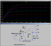
I had one more idea to improve the circuit I posted a couple of days ago - use a voltage divider to generate a small DC offset voltage matching the DC offset from the diode.
In the attached schematic, if the DMM is connected between Vo1 (red lead) and Vo2 (black lead), most of the DC offset will be gone.
There is still some non-linearity, which is inherent in the diode. It can be seen in the graph - those output lines are not quite equally spaced, even though the input AC voltage is incremented by equal 200 mV steps each time.
-Gnobuddy
Attachments
I suggested a very simple circuit, to make your life simple 🙂
You wanted to know output signal *capability* which I understand as "what is the maximum voltage my preamp can supply?" ,we are then talking about:
* a "single" number
* highest level possible
as in: "my preamp can supply 3V RMS" (or whatever) plus "I want a somewhat stable value I can quote, not a wildly swinging needle or worse, a garbled digital display".
Both answers are solved by the simple probe circuit I posted:
* the capacitor "holds" the peak value measured long enough so a needle stabilizes or a digital display can actually show "a number"
* RMS value is Vpp/2.8
You might have to add , say, .2 to .6 or 7 V DC to the peak value shown to compensate for diode drop but no big deal if we are talking, say, 3V RMS which amounts to almost 9Vpp .
By the way, a value which I did not choose at random, it´s about the maximum audio voltage in a 9V battery powered pedal or guitar preamp, so it´s very relevant to the question. 🙂
But now you want to measure down to 60 mV 😱
Ok, it can be done, of course, but now we have to compensate for diode drop.
Since you were brave enough to take multiple measurements, write down a table, draw a compensation or equivalence graph, etc. , then I guess you can complicate the circuit a little and let hardware help you.
This is a "perfect diode" circuit, also called "sample and hold" .... because it charges the capacitor to peak voltage and then holds it for long time so you can measure easily.
in fact it holds the peak voltage so much that you have to short the capacitor to discharge it for a new measurement.
Or you can add a resistor in parallel with the capacitor to self discharge it in a short time so you can "follow" different guitar output depending on strumming, chord or single note, fingerpicking vs. plucking, etc.
Try 1M in parallel with the 1uF cap, in that case you won´t need the reset switch because cap is being discharged all the time.
Circuits as shown are Lab type, the left one is fine if you load it with a digital multimeter, the right one is buffered to be able to drive "something else", think a compressor, an auto wah, a panel meter or Led, etc.
Adding the 1M resistor (might go down to 220k if you want it faster) will *very slightly* alter precision, but is WAY more than enough for your testing.
You can safely use a Si diode, such as 1N914 shown, 1N4148, and in a pinch even 1N4002, because Op Amp "huge" gain divides diode threshold by same factor.
Use TL072 Op amps, feed them +/-15V and add a 1M resistor from Vin to ground so when your guitar is unplugged it does not get crazy.
Almost forgot: since this is a peak rectifier, Vrms=Vp * 0.707
You wanted to know output signal *capability* which I understand as "what is the maximum voltage my preamp can supply?" ,we are then talking about:
* a "single" number
* highest level possible
as in: "my preamp can supply 3V RMS" (or whatever) plus "I want a somewhat stable value I can quote, not a wildly swinging needle or worse, a garbled digital display".
Both answers are solved by the simple probe circuit I posted:
* the capacitor "holds" the peak value measured long enough so a needle stabilizes or a digital display can actually show "a number"
* RMS value is Vpp/2.8
You might have to add , say, .2 to .6 or 7 V DC to the peak value shown to compensate for diode drop but no big deal if we are talking, say, 3V RMS which amounts to almost 9Vpp .
By the way, a value which I did not choose at random, it´s about the maximum audio voltage in a 9V battery powered pedal or guitar preamp, so it´s very relevant to the question. 🙂
But now you want to measure down to 60 mV 😱
Ok, it can be done, of course, but now we have to compensate for diode drop.
Since you were brave enough to take multiple measurements, write down a table, draw a compensation or equivalence graph, etc. , then I guess you can complicate the circuit a little and let hardware help you.
This is a "perfect diode" circuit, also called "sample and hold" .... because it charges the capacitor to peak voltage and then holds it for long time so you can measure easily.
An externally hosted image should be here but it was not working when we last tested it.
in fact it holds the peak voltage so much that you have to short the capacitor to discharge it for a new measurement.
Or you can add a resistor in parallel with the capacitor to self discharge it in a short time so you can "follow" different guitar output depending on strumming, chord or single note, fingerpicking vs. plucking, etc.
Try 1M in parallel with the 1uF cap, in that case you won´t need the reset switch because cap is being discharged all the time.
Circuits as shown are Lab type, the left one is fine if you load it with a digital multimeter, the right one is buffered to be able to drive "something else", think a compressor, an auto wah, a panel meter or Led, etc.
Adding the 1M resistor (might go down to 220k if you want it faster) will *very slightly* alter precision, but is WAY more than enough for your testing.
You can safely use a Si diode, such as 1N914 shown, 1N4148, and in a pinch even 1N4002, because Op Amp "huge" gain divides diode threshold by same factor.
Use TL072 Op amps, feed them +/-15V and add a 1M resistor from Vin to ground so when your guitar is unplugged it does not get crazy.
Almost forgot: since this is a peak rectifier, Vrms=Vp * 0.707
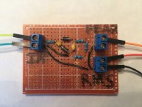
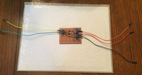
picture of my circuit, thanks guys
Thanks Gnobuddy for the interest and the circuit, that is a very interesting circuit.
I think those circuits are all great for teaching or use so I'm glad they were posted. (As far as measuring down to 60mv I'm simply posting what I found as I was curious. I cut and paste into mycurvefit.com which plots it and fits it automatically, so it only took a few minutes, doub't I'd ever use those formulas)
Anyhow, in practice, I've been using the simple voltage doubler charging the capacitor with the output across the voltage divider with 2 taps, I think that's simple and accurate enough for my purposes. Here is a picture I've already used it multiple times.
Thanks JMFahey for the circuit you posted, I'm very happy with the spinoff I did of it, its seems to be working fine and has been very useful. I like the idea of the voltage divider knocking down the output though. Its not that hard to divide by 2 and multiply by .7, 🙂 but it seems nice to me to just read the voltage right on the dmm etc.
Thanks again everyone
Attachments
- Status
- Not open for further replies.
- Home
- Live Sound
- Instruments and Amps
- Please help how to measure/guage output of guitar preamp