Stixx,
Don't stop them and their innovation spirit. Let them try.
Maybe they know more.
We have at least disclosed a solution that works.
Patrick
Don't stop them and their innovation spirit. Let them try.
Maybe they know more.
We have at least disclosed a solution that works.
Patrick
The biggest downside with the 317/337 is still the >3V dropout. especially on lower voltage circuits. We are still talking simple to220 devices with a few caps. Although it would be fun to A/B with a more "fancy" supply - if it did work that is.
i'm quite certain Salas would work - but you may need a small series resistor before the elyt caps, which maybe will degrade some of the performance. But still would be fun to compare.
I will probably remake my boards with LDO + cap multi though, to save some space in my case.
i'm quite certain Salas would work - but you may need a small series resistor before the elyt caps, which maybe will degrade some of the performance. But still would be fun to compare.
I will probably remake my boards with LDO + cap multi though, to save some space in my case.
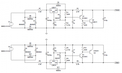
Has anyone made a PCB layout of the great PSU by Nazar?
S-Audio Systems - PSU for High end audio without electrolytic capacitors
I'd love to use it for this project and others but don't want to do it P2P...
Ciao!
Do
S-Audio Systems - PSU for High end audio without electrolytic capacitors
I'd love to use it for this project and others but don't want to do it P2P...
Ciao!
Do
Pinnocchio,
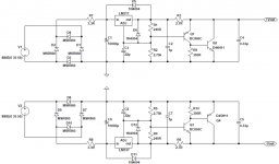
I am using a slightly "updated" version of the Nazar reg schematic. I am just building a second set P2P on 60x80 chinese proto board.
Actually quite easy to do.
Thanks Stixx,
The only thing about P2P is I don't like the final look. It always looks like an addon part of a project when mixing PCBs with proto boards. In my head, it looks like sonething that was never finished... Go figure... I must have a problem in the head... 😀
In the end, I might end up doing it P2P since I have no knowledge of PCB creation, although I should learn it eventually and be self dependent.
What is the outcome of the modifications you did on the circuit?
Thanks
Do
Fancy regulators are fine but in my case - I found that good CRCLC (2.2mF/0.22R/2.2mF/1mH and 10R parallel/4.4mF) followed by a simple 7815 or 7915 works beyond my expectaions. Absolutely no noise hiss hum etc. cannot tell it is even turned on. I don't know why it needs to be better than that. The humble 7815 seems to be the whipping boy of shunt regulator purists but shure works well here.
Dropout voltage !
Yes, you need about +3v above the regulated value for 7815 to work. But with a 15VAC trafo, I get about 21VDC after the cap filter so not a problem.
3V is a minimum. It won't give much headroom for the 7815/7915 when you take Uripple and the dropout voltage in account. Why not use LDO low noise regs and have more headroom, less hot regs and somewhat higher rail voltage ?!
With LDO regs you possibly can use a 2 x 12V transformer and still have 13 or 14V regulated DC.
With LDO regs you possibly can use a 2 x 12V transformer and still have 13 or 14V regulated DC.
Last edited:
I have a 15-0-15Vac transformer and it gives ±22Vdc, when under load of ~100mAdc.
At lowest UK mains of 226Vac it still gives ~±21Vac
That is plenty for a 2 to 2.5V drop out and much to spare to power a 317/337 regulator.
Yes, 6V to 9V across the 15V regulator.
At lowest UK mains of 226Vac it still gives ~±21Vac
That is plenty for a 2 to 2.5V drop out and much to spare to power a 317/337 regulator.
Yes, 6V to 9V across the 15V regulator.
No that much heat - I am using rather small local TO220 heatsinks and they are just warm to touch not hot. Depends on load and 100mA current is not much I guess. 600mW is not a lot from one of those regulators.
The only thing about P2P is I don't like the final look. It always looks like an addon part of a project when mixing PCBs with proto boards.
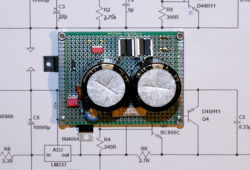
True, but it depends how you do the P2P. The Nazar I just built doesn't look too bad, doesn't it? And it uses BC860C in SOT23 underneath... a bit tricky to solder but doable.
Attachments
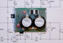
True, but it depends how you do the P2P. The Nazar I just built doesn't look too bad, doesn't it? And it uses BC860C in SOT23 underneath... a bit tricky to solder but doable.
You're right, I'm probably being too picky. I can do P2P and SMD without issues. I'll assemble one and see how I like it. In the end it is hidden in a case where no one will see. I used to do tons of P2P with Radio Shack circuit books when I was a teenager and really liked it. Mind you, it was the only thing I had back in the days with my big 150W Weller soldering gun! 😀
Let's have fun again! 😀
Do
Nice work.

Those Chinese veroboards are very handy and look decent too. I have never had a solder pad come off them. Reminds me, need to stock up on those again. 🙂
I used my last one on this amp as you may have seen:
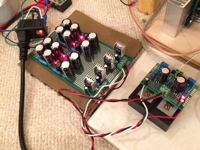
Btw, I do think BC546 and 547's could work in place of those BC860's.
Last edited:
D.L.Feucht discusses how to remove the output offset of a DC coupled jFET Buffer.
Excellent reference! Thank you.
RFC
This is what I have come up with for F5 using 2N5457/5460. I did this using version XVII, most recent available.
RFC, any and all.
You should use a low Idss pair of JFETs if you want to use the 5457/60.
This is what I have come up with for F5 using 2N5457/5460. I did this using version XVII, most recent available.
RFC, any and all.
Attachments
- Home
- Amplifiers
- Pass Labs
- F5 Headamp ?