Digikey order made.
Here's hoping whoever picks my Digikey/Mouser orders isn't too badly hung over from 4th 🙂
Hey, it could work out to your advantage!
BK
Attached the dimension gerber file.
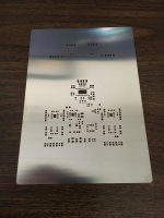
Looks like OSH has stainless stencils now. Nice.
Use "SSLAUNCH15" for a 15% OSH discount through 7/5. Their email encouraged sharing the code. I've always had good luck with their polyimide stuff, but I'm going to try SS this time.
BK
I know the tpa3250 spec says input resistance is 24k, I assume that is same as input impedance.
What is the input impedance of the the Wiener Pro input stage?
What is the input impedance of the the Wiener Pro input stage?
10k differential (input + to -), 1M common mode (either input to ground).
Sent from my Nexus 5 using Tapatalk
Sent from my Nexus 5 using Tapatalk
Use "SSLAUNCH15" for a 15% OSH discount through 7/5. Their email encouraged sharing the code. I've always had good luck with their polyimide stuff, but I'm going to try SS this time.
Awesome, thanks! I just used it with my order of a 3mil polyimide stencil.
10k differential (input + to -), 1M common mode (either input to ground).
Sent from my Nexus 5 using Tapatalk
Thanks.
I guess that means 10k for balance in and 1M for single end input.
That is a big difference between balance in and SE in.
So I guess for balance input, maybe better to bypass opamp stange and just connect direct into the tpd3250 via the transformer input holes.
10k differential (input + to -), 1M common mode (either input to ground).
Sent from my Nexus 5 using Tapatalk
Thanks.
What if I want to input for common mode? As I want to add a tube preamp which has 18dB gain, can I just input without passing thru the opamp?
The input impedance should be 10K regardless if you're using single ended or balanced input.Thanks.
I guess that means 10k for balance in and 1M for single end input.
That is a big difference between balance in and SE in.
So I guess for balance input, maybe better to bypass opamp stange and just connect direct into the tpd3250 via the transformer input holes.
The input circuit looks like Figure 20 in Bruno Putzeys' "G word" application note. My "Rcd" is 1M, and my "Ril/Rih" are 4990 ohms, which sum to about 10K:
http://www.hypex.nl/docs/papers/The G Word.pdf
My input terminal blocks have three terminals, +/-/ground. For balanced input, cable shield should be connected to ground, and signals connected to +/-. For single ended input, input signal should go to +, and input ground should go to both - and ground. You can connect the input ground to just the - terminal, provided you can ensure the source ground and the Pro's ground are connected via some other means (via the AC power ground or whatever).
Also, unless you're using a transformer (which removes any common mode signal and guarantees signal symmetry), I would highly advise using the input stage.
The TPA3250 doesn't have "true" differential inputs, but rather two single ended inputs side by side that it independently amplifies. Common mode signal on the inputs will be amplified and appear as a much larger common mode signal on the outputs - with large common mode signals potentially driving the amplifier into clipping, or some of the common mode signals showing up as differential mode on the outputs and causing audible noise/distortion.
And if the inputs aren't symmetric (say, one input has twice the magnitude of the other input) then the outputs will be unbalanced as well, and you'll only be able to get 2/3 as much power out of the amplifier before the higher output signal starts clipping.
The input stage is designed to fix all this - rejecting common mode interference and making a symmetric drive signal for the TPA. Think of it as an active transformer 🙂
Mouser parts arrive today and stencil showed up yesterday.
The SS stencil looks really nice. The first thing you notice compared to polyimide is that all the corners are perfectly square, and of course it doesn't flop around. Shame I'll probably use it just once, but only the best for my Wiener.
BK
The SS stencil looks really nice. The first thing you notice compared to polyimide is that all the corners are perfectly square, and of course it doesn't flop around. Shame I'll probably use it just once, but only the best for my Wiener.
BK
Attachments
Gotta say, stainless stencils are so much nicer to work with than the poly ones. And they do last a lot longer.
Haven't got to building cards yet, but I just put my PID reflow controller in a proper box to make it a little less electrocutey/catch-on-firey.


Case is a Hammond 1598C instrument box with proper fire ratings. I'm using a big 30A rated mechanical relay to switch on/off the load. Power for the controller/relay is fused and switched, and I poked a USB/RS485 interface in there to allow remote control and easy setup of the controller.
I wish panel mount thermocouple jacks were easy to come by and cheap, but it's only 2 screws to take the case apart and 2 more to undo the thermocouple from the back of the PID, which isn't too bad.
Haven't got to building cards yet, but I just put my PID reflow controller in a proper box to make it a little less electrocutey/catch-on-firey.
Case is a Hammond 1598C instrument box with proper fire ratings. I'm using a big 30A rated mechanical relay to switch on/off the load. Power for the controller/relay is fused and switched, and I poked a USB/RS485 interface in there to allow remote control and easy setup of the controller.
I wish panel mount thermocouple jacks were easy to come by and cheap, but it's only 2 screws to take the case apart and 2 more to undo the thermocouple from the back of the PID, which isn't too bad.
Last edited:
I wish panel mount thermocouple jacks were easy to come by and cheap
I'm not sure what thermocouple type you are using, but I have some type T panel jacks / plugs from Omega (SMPW-CC-T-M, MPJ-T-F). These are surplus from another PID project (espresso machine) and I would gladly send you a pair to help the Wiener Cause.
Awesome. I only checked mouser/digikey for sockets. Right now I'm using K type thermocouples, and I can more than get by with what I've got. Thanks for the offer though.
Curious about this espresso machine. Is it worth all the work to get the temperatures/pressures/whatever exact?
Curious about this espresso machine. Is it worth all the work to get the temperatures/pressures/whatever exact?
Curious about this espresso machine. Is it worth all the work to get the temperatures/pressures/whatever exact?
"Worth it" is always a tricky term in most DIY projects 🙂. I modified a Rancilio Silvia which is considered a great deal if you need a solid single boiler machine. The underlying problem is that without a PID for the brew temperature, there is quite a large swing (58F swing!) between when the heating elements are triggered on or off by the built in thermostats. However, heating techniques called "temperature surfing" help get a more accurate temp at the time of extraction. If you incorporate that into your espresso ritual, it's not a big deal to get close to the desired temps without swings.
This inefficiency drove me to find a better solution and proved to be a fun project to design from scratch. After looking at the various off the shelf mods (using pre-assembled PID units, etc), I decided to design my own using an Arduino Yun and a thermocouple shield designed for coffee roasters . Overall, I implemented 2 thermocouples to monitor the boiler temperature and the temperature of the brewgroup at extraction. I also added a 4 channel opto-isolator so I could monitor the existing mains voltage front panel switches for switching between brew and steam temperatures and also monitor the shot timing in software. The software consisted of monitoring, relay control, a tuned PID algorithm on the arduino and logging to a Golang based frontend that graphed the temperature and displayed different heating states. Code and a screenshot is up at https://github.com/gregose/PIDuino.
I could probably go on talking about the implementation forever, but in the end it was a fun project. Was the espresso notably better? I never A/B tested it and can't say exactly, but the numbers say it should be better 🙂
Last edited:
Awesome. Thanks for the info. I'm sure there's some effective "coffee THD" number that drops from 0.01% to 0.005% in your done up espresso machine. Which makes all the difference 😉
Current state of things: finally spent a good night at things tonight. Got the toaster oven instrumented and the PID controller tuned in, and all my parts (excepting moisture sensitive ones) taken out of cut tape and stuffed into a component bin with pull out trays.
I'm ready to paste and reflow my first Pro board, but it's 12:20AM on a Sunday night and tomorrow's my better half's birthday, so I should be back at it on Tuesday.

First Pro built. Stenciled, parts placed with tweezers and reflowed in the toaster oven. Having all my parts organized definitely made this job go quicker.
Bringing it into work tomorrow to inspect solder joints, and slowly powering it up on a bench supply to verify the power supplies are all good. Fingers crossed.
Applied power to the thing, didn't go bang. +-12V rails measure as they should, the LM25018 "fly-buck" converter is doing its job.
Next up, seeing if the ATTiny20 programs at 3.3V. If it doesn't, bringing up the board is going to be a much bigger pain in the *** 🙂
Next up, seeing if the ATTiny20 programs at 3.3V. If it doesn't, bringing up the board is going to be a much bigger pain in the *** 🙂
Next up, seeing if the ATTiny20 programs at 3.3V. If it doesn't, bringing up the board is going to be a much bigger pain in the ***
Good luck. Just so I fully understand the issue, I've tried to recap my understanding: The attiny is powered by U3, the 3.3v reg, and you were planning on doing the programming via the TP1 header in-circuit? The Atmel TPI datasheet says you need to program over 5v. I am assuming you can't temporarily power via the TP1 header because connected components are not 5v tolerant.
Are you still waiting on the TSSOP socket to program it out of circuit? One option to provide an option to upgrade the firmware in-circuit in the future might be to flash a bootloader out-of-circuit, maybe something like TinySafeBoot - A tiny, safe and flexible AVR-Bootloader for ATtinys and ATmegas, and then use 2 of the pins accessible on TP1 for UART programming.
Regardless, the assembled board looks beautiful and congrats on the power bring up. Anxiously awaiting if 5v in the TPI spec was just a "recommendation!"
Applied power to the thing, didn't go bang. +-12V rails measure as they should, the LM25018 "fly-buck" converter is doing its job.
Nice, how do the rails measure regarding noise/ripple/imbalance?
- Home
- Group Buys
- "The Wiener" TPA3118 amplifier, group buy #3 + "Wiener Pro" prototypes.