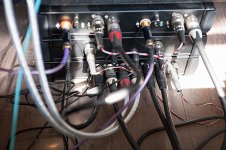
I did not use a pot but a 32 step logarithmic attenuator with 2dB / step.
For this I designed my own remote control. See the top cabinet.
View attachment 548917
Hans
Hans,
Can you show us the back panel ?
Also, do you have the mechanical drawing of the back panel to show us?
I am considering buying a chassis from a China vendor who will do CNC drilling for me.
Other members can show their back panel if they have done it.
Hans,
Can you show us the back panel ?
Also, do you have the mechanical drawing of the back panel to show us?
I am considering buying a chassis from a China vendor who will do CNC drilling for me.
Other members can show their back panel if they have done it.
Here it is

It is the chassis at the bottom, with just the 2 input channels that the BPBP has.
The plug at the far left is from a separate SMPS for the display.
The plug at the far right comes from the middle cabinet, giving a stabilized supply of +/- 18Volt through Jung Regulators.
The top cabinet is my balanced Phono Preamp.
Hans
if the relays and circuits draw 100mA and one wants to keep the regulator dissipation to 500mW, then the Vdrop across the regs should be 0.5W/0.1A = 5Vdrop.
That equates to 12Vout and 17Vin at the second smoothing capacitor.
There are two further Vdrops at the melf resistors. That might equate to ~17.5Vdc at the rectifiers.
13Vac fully loaded would give 18.4Vpk and subtract one diode drop in each polarity for a final ~17.7Vdc at the rectifiers. A bigger transformer not dropping down to the fully loaded secondary voltages may give an even higher Vin.
If my numbers are about right, then 13Vac is about the maximum one can use for these regulators.
Last edited:
I don't think so, but I'll put a DXF together 🙂Did anybody publish - in another thread maybe - any accurate drawing of the back plate?
Xavier, it is great.
Thank you.
Sorry Arthur, I don't understand.
I'm down to the last assembled board now. One GB person who was on the waiting list might take a set from someone else on the GB who doesn't want it. In this case, one lucky person might get the last board...
I'll have a few bare PCBs left, maybe two or three which I'll offer to those on the waiting list. Also one or two Hypex regs left. Then, we're done for this GB 🙂
There are still a few people who haven't confirmed receipt of their boards - please let me know so I can mark your order off the list.
Thanks.
Then, I'm off to the pub for a
 or two! What a mammoth effort!
I don't think so, but I'll put a DXF together 🙂
IIRC the 6 connectors are at 1inch pitch, and the connector drawings are available from the Neutrik site.
Jan
They're not quite 1 inch, they're in fact 23mm, except that one of them is a tad more, like 23.1mm or something like that. I'll need to measure.
OK, the well-intentioned masochist in me has requested a quote for another small batch of assembled boards. If pricing is OK, I'll consider doing another run as I keep getting requests for more of these great little preamps.
If have a question regarding the pot connection on the pcb.
We have from the BPBP schematic a dual pot connected to two dual opamp's LM4562 (U2/7B pin 6 [B-] and 7 [Bout], and U2/7A [Aout]) pin.
Minimum volume when pin 6 and 7 are 0 ohm through the pot turned CCW.
If I follow the pcb lines for pot 1 (on the edge) they go left to right; to pin 1, 2, 7 (Aout, A-, Bout)
Pot 2 (inner connection) goes left to right to pins 7, 6, 1 (Bout, B-, Aout)
I can understand pot 2 for its connection, but I can't follow that pot 1 is connected to A- ???
Can someone explain that? I checked it 3 times...
Btw,
The LM4562 pin layout is:
1: Aout, 2: A-, 3: A+, 4: V-
5: B+, 6: B-, 7: Bout, 8: V+
the sch has swapped the a and b of one of the dual opamps.
is that the confusion?
Thanks, L and R use different path for routing reasons I guess...
- Home
- Group Buys
- Bruno Putzeys Balanced Preamp - Group Buy Part 2