No reference to GND at input and output thus risks for plops when connecting cables. No protection against cable capacitance, No HF/RF input filtering. No DC blocking at either input or output. No muting relay so burned "woofer syndrome" when wrong power on sequence is done.
Not suitable for generic use.
Yes, sure. This is a "building block" - that's what 's been requested initially for impedance matching.
If it will be used standalone, I would also add some gain stage in front of it. And of course an input network with RF filter and ground reference.
Don't treat it as a "finished product". This is a buffer cascade.
That is OK if that is clear to possible builders. IMHO it is better to publish the final complete schematic as chances are likely that some people will copy it like it is now, incomplete and with some risks. I notice a low level of generic knowledge these days with younger audio DIYers so we shouldn't assume they are on the same level of knowledge the experienced members here have. Anyhow, when things don't work out OK you know who is blamed.
Last edited:
That is OK if that is clear to possible builders. IMHO it is better to publish the final complete schematic as chances are likely that some people will copy it like it is now, incomplete and with some risks. I notice a low level of generic knowledge these days with younger audio DIYers so we shouldn't assume they are on the same level of knowledge the experienced members here have. Anyhow, when things don't work out OK you know who is blamed.
Agreed - I take a point of being more careful with publishing such things (in most cases, I publish rather "productised" designs).
Agreed - I take a point of being more careful with publishing such things (in most cases, I publish rather "productised" designs).
Hi guys, I read our conversations, but if you use it only as a simple buffer to be connected to the preamp in the page # 12 .... .... I have problems? ... Do not make me worry!..😕

Hi guys, I read our conversations, but if you use it only as a simple buffer to be connected to the preamp in the page # 12 .... .... I have problems? ... Do not make me worry!..😕
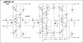
I suggest you APEX P30 preamp, there is nice PCB made by alexmm and stil4given test it.
http://www.diyaudio.com/forums/solid-state/164093-100w-ultimate-fidelity-amplifier-668.html
Attachments
Hi guys, I read our conversations, but if you use it only as a simple buffer to be connected to the preamp in the page # 12 .... .... I have problems? ... Do not make me worry!..😕
That's ok - I assumed it would be connected to the output of that pre-amp (post #12) and then the power amp has got a DC blocking cap at the input.
Add GND reference too. And power on/off muting. You see , it really has benefits to publish designs that are ready/DIY friendly. Saves a lot of writing, questions and error correcting 😉
Last edited:
I suggest you APEX P30 preamp, there is nice PCB made by alexmm and stil4given test it.
http://www.diyaudio.com/forums/solid-state/164093-100w-ultimate-fidelity-amplifier-668.html
Preamp ... interesting .... Congratulations
That's ok - I assumed it would be connected to the output of that pre-amp (post #12) and then the power amp has got a DC blocking cap at the input.
..thanks ... for clarification ..
Add GND reference too. And power on/off muting. You see , it really has benefits to publish designs that are ready/DIY friendly. Saves a lot of writing, questions and error correcting 😉
you can clarify .... better? missing something?
.... here it is over ...... working properly .... Of course, all those LEDs lit give a Christmas effect 😀😀 .... I listen to it I try to understand how it sounds ......
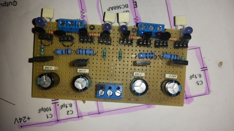
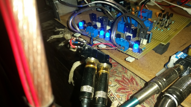
Are these LEDs blue, or am I color blind?
Blue LED has voltage drop of 3.3V, while red LED has 1.8V.
This will make a difference; I think these LEDs must be red - or replace each LED with 3 'normal' diodes 1N4148 to achieve the same voltage drop (0.65V each 1N4148).
Valery marked these LEDs as red for a reason.
Blue LED has voltage drop of 3.3V, while red LED has 1.8V.
This will make a difference; I think these LEDs must be red - or replace each LED with 3 'normal' diodes 1N4148 to achieve the same voltage drop (0.65V each 1N4148).
Valery marked these LEDs as red for a reason.
Last edited:
Are these LEDs blue, or am I color blind?
Blue LED has voltage drop of 3.3V, while red LED has 1.8V.
This will make a difference; I think these LEDs must be red - or replace each LED with 3 'normal' diodes 1N4148 to achieve the same voltage drop (0.65V each 1N4148).
Valery marked these LEDs as red for a reason.
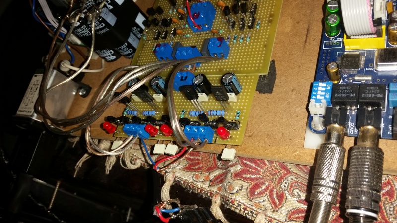
Exactly 🙂 LEDs are used as reference voltage sources, the voltage we get with the blue ones is almost doubled, comparing with the red ones. As a result, the quiescent currents are much higher in the circuit. In order to decrease them back to initial values, R1 and R2 have to be 560R if the blue LEDs are used.
Are these LEDs blue, or am I color blind?
Blue LED has voltage drop of 3.3V, while red LED has 1.8V.
This will make a difference; I think these LEDs must be red - or replace each LED with 3 'normal' diodes 1N4148 to achieve the same voltage drop (0.65V each 1N4148).
Valery marked these LEDs as red for a reason.
Is they are LED BLU , when not those red LED ..... I used them just to check if everything is ok . Today I buy the red LEDs .....
Exactly 🙂 LEDs are used as reference voltage sources, the voltage we get with the blue ones is almost doubled, comparing with the red ones. As a result, the quiescent currents are much higher in the circuit. In order to decrease them back to initial values, R1 and R2 have to be 560R if the blue LEDs are used.
OK....
Is they are LED BLU , when not those red LED ..... I used them just to check if everything is ok . Today I buy the red LEDs .....
Just as a pre-caution - when you use blue LEDs instead of the red ones, the quiescent current of all the transistors in the buffer practically doubles - for MJE3XX ones it becomes 21mA instead of 11.5mA.
Not a big issue with +/-24V rails, but in some high-swing power amp design with +/-75V rails, those transistors would be seriously over-heated, if not fried to death (unless a decent heatsink is in place).
So... color matters 😉
received message ..... as I said above, today I replace with red LED (Red ... Ferrari ...😀😀.)
received message ..... as I said above, today I replace with red LED (Red ... Ferrari ...😀😀.)
Yes, I was writing mine at the same time with your "OK" 😀
put on red LED ...... now I tested the Buffer + Preamp is functioning properly . I only detected the presence of noise that suggests power , perhaps because united with that of the preamp ...
- Status
- Not open for further replies.
- Home
- Amplifiers
- Solid State
- Diy preamp for Amplifier IRFP240/IRFP9240