Grounding looks great! Well done!
Add a few vent holes as discussed and enjoy your amp for many years!!
😀 😀 😀
Add a few vent holes as discussed and enjoy your amp for many years!!
😀 😀 😀
I will report back on what method of ventilation can be achieved easiest
Spacer mod looks like is winning at the moment

FR
Spacer mod looks like is winning at the moment
FR
Grounding looks great! Well done!
Add a few vent holes as discussed and enjoy your amp for many years!!
😀 😀 😀
Thanks
My moto is
If it's worth doing then Do it once & Do it right
FR
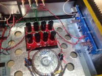
Certainly a nicely done neat build.
Curious though as to the rationale for the reflective Insulation pads .. anti vibration notions?
Is the Box that flimsy ?
Curious though as to the rationale for the reflective Insulation pads .. anti vibration notions?
Is the Box that flimsy ?
Certainly a nicely done neat build.
Curious though as to the rationale for the reflective Insulation pads .. anti vibration notions?
Is the Box that flimsy ?
The amp case is solid enough however it's a combination of alloy and steel sheet
Because the amp components take up so little realestate we still effectively have a drum chamber inside the case
The addition of the damping material to the sheet metal parts is to absorb vibrations from within and from outside sources e.g. Bass vibrations.
I'm sure all will agree that ones body feels audio vibrations so it stands to reason that a mostly empty component would as well, especially when it's only a foot or two away from the speaker.
That's my rational, but I would be happy to be corrected
FR
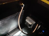
Thought it was about time for an update
Just before Christmas I noticed the slightest of hums in the bass section
The only reason I actually noticed this hum was because I was sitting directly in front of the speaker while choosing a record to play ( as you do ) because it can take some time to decide 😉
Anyway after the holidays, my associate put the amp on his Rigol tester and found a small anomaly
So we decided to rewire the power lines and the earth points in the previous configuration that was on the F5
This fixed the hum issue completely
Please see photos of new redirected wiring
P.S. Still enjoying the F6 immensely
FR
help me, are you sporting two text book ground loops in your pictures?
That is 2 x (PSU board - amp board - speaker post - PSU board)?
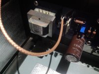
Earth points are as follows
Upon testing on the Rigol - there was ~70mv wideband noise when wired as per original design.
Changing the earth wiring to this scheme in the photos has reduced it to ~20mv Wideband.
It is now basically star earthed at the speaker binding posts.
What is hard to see is the (black) earth wire running from the RCA
grounds to the 'negative' binding post as well.
Red and Black wires from filter board to F6 boards are Negative and Positive rails.
Green from filter board ( 0v) moves from F6 board 0v and now goes to
speaker Negative posts.
Chassis earth goes to speaker Negative posts via a CL60
RCA earths go to the F6 boards (sheild) and (black wire) to the
speaker Negative posts.
All wiring is silver coated OFC copper from Speaker Bug- Wire
Also the main power supply wire is shielded
Hope that helps
FR
Last edited:
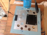
An air circulation update so ZenMod doesn't get angry at me 😉
So today is Sunday and I decided to remove the whole baseplate and tackle the air circulation that ZenMod mentioned
After mulling over some ideas I settled on 5 holes on each side = 10 X 32mm
In a triangular configuration
Next week I will raise the amp feet by approx 10mm for underside air circulation
And I will also add some perforated plate on the underside to keep any inquisitive insects that want to explore
See mockup of the perforated plate in the photo - right side
So the F6 all back together again now
FR
Attachments
My associate commented that a redneck would have just shot the base plate for target practice to add the holes 🙂
FR
FR
Attachments
Last edited:
Thanks for clarifying. I got confused by the wire colors.RCA earths go to the F6 boards (sheild) and (black wire) to the
speaker Negative posts.
Do you leave the RCA shields floating at the PCB ends?
Thanks for clarifying. I got confused by the wire colors.
Do you leave the RCA shields floating at the PCB ends?
The shields are connected to earth at PCB and at RCA terminal
You will see that elusive black wire to earth as well
FR
Attachments
Last edited:
i don't want to sound picky, but wouldn't this consititute a ground loop: RCA - board - speaker post - RCA?
i don't want to sound picky, but wouldn't this consititute a ground loop: RCA - board - speaker post - RCA?
Others with more electronics knowledge would probably answer that better than me
( I am a mechanical engineer with good soldering skills 😉 )
All I know is that it was wired as per instructions - and I got a hum
Wiring was changed to what I have posted earlier and it's fixed the issue
FR
Fixing the issue its what its all about.
I just find it difficult to draw conclusions...
To add some more light
Keep in mind that this is an upgrade build from the F5 to the F6
Reworking the wiring is going back in the style of the F5 so I can't claim to have invented it as its been done before
FR
Earth points are as follows
Upon testing on the Rigol - there was ~70mv wideband noise when wired as per original design.
Changing the earth wiring to this scheme in the photos has reduced it to ~20mv Wideband.
FR
May I ask you if yoy really meant mV as millivolt or maybe microvolt?
May I ask you if yoy really meant mV as millivolt or maybe microvolt?
mV = millivolt
uV = microvolt.
Normal metric standards shall apply.
Not sure if in the USA, a different ID system is used ?
FR
mV = millivolt
uV = microvolt.
Normal metric standards shall apply.
Not sure if in the USA, a different ID system is used ?
FR
MV = Mega volt...Zenmod recently razzed me on this...
Last edited:
Thanks for clarifying. I got confused by the wire colors.
Do you leave the RCA shields floating at the PCB ends?
For what its worth, mine float on both ends....total silence.
Russellc
- Status
- Not open for further replies.
- Home
- Amplifiers
- Pass Labs
- Upgrade F5 to F6