any 12v 0.5w will do. example of ZF12 here. https://www.reichelt.com/Diodes-Z-0-5W/ZF-12/3/index.html?ACTION=3&GROUPID=2993&ARTICLE=23114.Will these work for the 12V zeners in the FX8, or do I need to get higher wattage diodes?
1N5242B Fairchild Semiconductor | Mouser
Thanks...
FX8 is my new favorite amp and FX9 is new idea for CFA with laterals.
Mr. Mile.
You are churning out amps faster than us (poor diyer's) can build, except Terry of course😀.
reg
Prasi
P.S. Successful in making FX-8 pcb in the third attempt and board populated. Will test tomorrow.
Hi Terry, Prasi,
Got my 2 FX8 up and running. They really do sound sweet. Need some more burn in to do honest compare. i used BD139/140-16's as thats all i had at the moment. Bias set at 130mv and dc offset was from -.2 to +.2mv. All very Easy to Build & set up. Running +-36V from Apex PSU.
Rick.
Got my 2 FX8 up and running. They really do sound sweet. Need some more burn in to do honest compare. i used BD139/140-16's as thats all i had at the moment. Bias set at 130mv and dc offset was from -.2 to +.2mv. All very Easy to Build & set up. Running +-36V from Apex PSU.
Rick.
Hi Terry, Prasi,
Got my 2 FX8 up and running. They really do sound sweet. Need some more burn in to do honest compare. i used BD139/140-16's as thats all i had at the moment. Bias set at 130mv and dc offset was from -.2 to +.2mv. All very Easy to Build & set up. Running +-36V from Apex PSU.
Rick.
Hi Rick,
Great News. Do share photos, if taken and also your comparison once you do it.
reg
Prasi
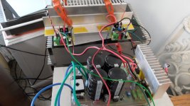
OK. It's all kinda of rough,but it works.
I would call it clinical.Nice job🙂. Wait till you see mine. guaranteed to be Messy!

reg
Prasi
Great job Rick! I'm sure the BD139/140 will work perfectly. How hot do they run on those little heatsinks? I have wondered if that would be a better way than mounting them on the main heatsink like I did. Those Latfets run pretty hot.
Blessings, Terry
Blessings, Terry
Bias set at 130mv and dc offset was from -.2 to +.2mv.
Wow...that's some really low voltages. Did you try to match Q1 and Q2 or did you use 2 random transistors?
Where do you measure the bias while adjusting the trimmer?
Thanks...
Terry,
They run very comfortably with those little heatsinks. Haven't Tried BLASTING For a long time with them yet! I choose to mount the latfets that way for my future heatsink requirements.
Ammel68,
I used a Peak Atlas DCA55 to group them. Not very closely either. hfe +- 5 to 7 between them. Measure bias with dmm in Amp mode on +plus rail
Last edited:
Using Dmm in Amp mode on +Plus rail.
Easy enough...much appreciated.🙂
Terry,
They run very comfortably with those little heatsinks. Haven't Tried BLASTING For a long time with them yet! I choose to mount the latfets that way for my future heatsink requirements.
Ammel68,
I used a Peak Atlas DCA55 to group them. Not very closely either. hfe +- 5 to 7 between them. Measure bias with dmm in Amp mode on +plus rail
I was wondering that. They might run cooler on their own sink. The Latfets like to run hot. I don't know if it would be better to keep them cooler. Maybe Mile can chime in and let me know.
Thanks Rick. Where do you measure the bias?
Another (safer ) method would be to put a 0.5-1 W resistor (say 22ohms) in series on each supply rails and measure the voltage drop across each of these resistors. You can then calculate the bias current using ohms law and adjust the pot to have 130mA. use reading on any one rail (say +ve rail).
reg
Prasi
Prasi,
You are of course correct. I normally use a 5W 10R on both +- sides. I have seen them Smoke, but it saved me a bunch of parts. I got ahead of myself this time and got Lucky!
Still listening & sounding GOOD.
You are of course correct. I normally use a 5W 10R on both +- sides. I have seen them Smoke, but it saved me a bunch of parts. I got ahead of myself this time and got Lucky!
Still listening & sounding GOOD.
'In a non-switching class AB amplifier none of the output transistors is switched off completely at any time.
In a class A amplifier normally a current increase in one output transistor goes together with an (almost) equal decrease of current in the other.
In a class AB amplifier normally an increase in current through one output transistor (with approx the bias current) makes the other transistor non-conducting.
In a non-switching cass AB amplifier an increase in current through one output transistor lowers the current in the other transistor in a non-linear way and such that it will not go to zero. The advantage is that this transistor will not be reversed biased (as will happen in normal class AB) and this makes switching on again much faster.
Steven'
There is a Doug Self's patent for new XD class amplifiers, which is another version of non-switching amplifier. I do not know the details but I suppose that it uses some kind of advanced non-switching technique. I am inclined to think of QUAD's "Current dumping" as some kind of non-switching amplifier too.
Hi,
First off finally you guys noticed,Second thanks to Sonal for the suggestions.
Thank you very much.
Yes off course,that is why I mentioned that I used 50Ohm and got the voltage reading of .9 or so.
Yes Sonal as well had suggested that I use 2.2K there instead of 1K. Will try that soon (have to buy some multiturn pots). Just for the test I used 10Ohm I had and put inplace of the fuse,The voltage reading is .9 to 1V on the positive side and 1-1.2V on the negative side. Now this corresponds very high bias but still the heatsink barely even warms up after multiple hours of keeping it switched on or an hour or so of playing music (moderate volume levels). So Am totally confused as to what's happening here.
I did want to push to the brim (just for testing purpose) and turn the bias preset almost full (50-60ohms),and the devices started heating within seconds and in no time was very very hot and before I could react one of the output blew (A1943)along with the 5A fuse.So I reverted back to the original setting and have left it at that.
Yesterday I was able to get A970 (which earlier was not able to get),So replaced all the 5401 with A970 ! Also replaced the 547 generic make with Philips make,Now the offset of between -5mv to -6mv.So will let the new transistors burn a bit before trying your suggestion.
On a different note,What are the better sounding options I can try in this ?? Am aksing cause I read in the old post that 970 was better sounding (suggested by Mr.Mile) and I replaced the 5401, I Also plan to replace few caps with Silver Mica,Already have Siemens Epcos MKP 10mfd for input. So want to use the best of the best possible to squzee as much detailed sound as possible from AX14-T.
Can I use 2N2222 (Metal package ) instead of 547 ? Please do suggest all the possible upgrades.
Regards.
First off finally you guys noticed,Second thanks to Sonal for the suggestions.
Regarding your post #6200:
Very nice work!!!
Thank you very much.
1. In my post #6150 I wrote to use 15-20R on rails, current limmiters safetys for first turn ON.
The voltage drop will be in 0,3-0,5V range, With different current limiters (40-50R), differents voltage drops also.
Yes off course,that is why I mentioned that I used 50Ohm and got the voltage reading of .9 or so.
2.The V_be multiplier (Bias ADJ) needs some mA current from VAS to work properly.
The V_be voltage = 0,7V * ( 1 + R_bc / R_be)
R_bc (base to collector) = R16 = 1K
R_be (base to emitter) = 220R + 1K trimmpot (R17 + trimmpot)
for Q V_be use BD139 or any NPN 50+V, 150+mA, 5+W, h_fe 100+
Output is a double emitter follower so we need 3,5 - 4,0VDC for V_be multiplier voltage to bias the output properly.
for 4.0VDC V_be voltage with R_bc = 1K
R_be must be 220R or a little bit lower
Probably with trimmpot adjusted to 0R the V_be voltage is in the 3,5VDC range or lower and you cannot adjust bias properly.
use 1K2 - 1K5 for R16 instead of 1K
Yes Sonal as well had suggested that I use 2.2K there instead of 1K. Will try that soon (have to buy some multiturn pots). Just for the test I used 10Ohm I had and put inplace of the fuse,The voltage reading is .9 to 1V on the positive side and 1-1.2V on the negative side. Now this corresponds very high bias but still the heatsink barely even warms up after multiple hours of keeping it switched on or an hour or so of playing music (moderate volume levels). So Am totally confused as to what's happening here.
I did want to push to the brim (just for testing purpose) and turn the bias preset almost full (50-60ohms),and the devices started heating within seconds and in no time was very very hot and before I could react one of the output blew (A1943)along with the 5A fuse.So I reverted back to the original setting and have left it at that.
3. For DC offset issues
IF DC offset is positive (+ 20mV) solder in parallel to R14 (220R) a 47K - 100K trimmpot
Adjust for zerro reading, desolder trimmpot, then look for trimmpot value and solder first nearest resistor value in parallel to R14.
IF DC offset is negative, same procedure with R15
Yesterday I was able to get A970 (which earlier was not able to get),So replaced all the 5401 with A970 ! Also replaced the 547 generic make with Philips make,Now the offset of between -5mv to -6mv.So will let the new transistors burn a bit before trying your suggestion.
On a different note,What are the better sounding options I can try in this ?? Am aksing cause I read in the old post that 970 was better sounding (suggested by Mr.Mile) and I replaced the 5401, I Also plan to replace few caps with Silver Mica,Already have Siemens Epcos MKP 10mfd for input. So want to use the best of the best possible to squzee as much detailed sound as possible from AX14-T.
Can I use 2N2222 (Metal package ) instead of 547 ? Please do suggest all the possible upgrades.
Regards.
Last edited:
- Home
- Amplifiers
- Solid State
- 100W Ultimate Fidelity Amplifier