I have a vintage audio amp I built from a kit many years ago.
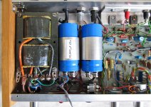
It has an unusual centre tapped mains transformer (see photo).
This transformer is not the one specified in the original design but it is the one that was supplied with the kit.
Does anyone understand how this type of double shell, ‘figure of 8’ transformer works?
I've tried in vain to find information on the web.
It looks as if it may be expected to behave like two separate transformers with the primaries connected in series and the secondaries connected in series with the midpoint acting as the centre tap.
In the amp, a single bridge rectifier (4 diodes) is connected between the two secondaries to give dual polarity supply rails (+/-28v unloaded). The centre tap is grounded.
The observed behaviour of this transformer is that the current in one secondary seems to affect the other, implying there must be at least some magnetic coupling between the two.
This effect leads to a voltage imbalance between the two supply rails unless the currents in the two secondaries are exactly matched.
From measurements I have made, a current mismatch between the two rails of just 18mA or so gives a voltage imbalance of about 5V. This is with a common mode current of 80mA (700 Ohms between the +ve and -ve rails). The 18mA current imbalance comes about because of the transitor biasing arrangement used in the power amp: Each channel draws an extra 9mA from the +ve rail to ground.
Unequal rail voltages like this are obviously undesirable because a +ve going signal will clip before the -ve.
If I add an extra 1.5K resistor to the -ve rail to balance out the currents, this brings the rail voltages back to the desired +/-28V.
Another solution might be to separate the two secondaries and use two separate full wave bridge rectifiers. Unfortunately, that introduces an extra diode voltage drop.
I have also tried replacing the transformer with a conventional centre tapped torroidal. When I do that, the voltage imbalance goes away - even with unequal load currents. Unfortunately this solution is impractical as a torroidal transformer with the right VA rating will not fit in the existing case.
I'm still trying to understand why the existing transformer behaves in this way.
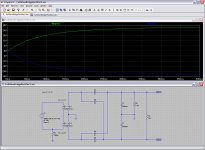
I've tried using LTSpice to simulate two non-magnetically coupled transformers connected as described. The results indicate that unless there is a really large difference in current between the two secondaries (more than 10:1), the two secondary voltages remain pretty much the same.
Can anyone shed some light on what’s going on here and offer an explanation?
It has an unusual centre tapped mains transformer (see photo).
This transformer is not the one specified in the original design but it is the one that was supplied with the kit.
Does anyone understand how this type of double shell, ‘figure of 8’ transformer works?
I've tried in vain to find information on the web.
It looks as if it may be expected to behave like two separate transformers with the primaries connected in series and the secondaries connected in series with the midpoint acting as the centre tap.
In the amp, a single bridge rectifier (4 diodes) is connected between the two secondaries to give dual polarity supply rails (+/-28v unloaded). The centre tap is grounded.
The observed behaviour of this transformer is that the current in one secondary seems to affect the other, implying there must be at least some magnetic coupling between the two.
This effect leads to a voltage imbalance between the two supply rails unless the currents in the two secondaries are exactly matched.
From measurements I have made, a current mismatch between the two rails of just 18mA or so gives a voltage imbalance of about 5V. This is with a common mode current of 80mA (700 Ohms between the +ve and -ve rails). The 18mA current imbalance comes about because of the transitor biasing arrangement used in the power amp: Each channel draws an extra 9mA from the +ve rail to ground.
Unequal rail voltages like this are obviously undesirable because a +ve going signal will clip before the -ve.
If I add an extra 1.5K resistor to the -ve rail to balance out the currents, this brings the rail voltages back to the desired +/-28V.
Another solution might be to separate the two secondaries and use two separate full wave bridge rectifiers. Unfortunately, that introduces an extra diode voltage drop.
I have also tried replacing the transformer with a conventional centre tapped torroidal. When I do that, the voltage imbalance goes away - even with unequal load currents. Unfortunately this solution is impractical as a torroidal transformer with the right VA rating will not fit in the existing case.
I'm still trying to understand why the existing transformer behaves in this way.
I've tried using LTSpice to simulate two non-magnetically coupled transformers connected as described. The results indicate that unless there is a really large difference in current between the two secondaries (more than 10:1), the two secondary voltages remain pretty much the same.
Can anyone shed some light on what’s going on here and offer an explanation?
Attachments
Last edited:
Another point I forgot to mention…
Initially I wondered if a possible explanation might be as follows:-
If there were no magnetic coupling between the two transformers, and the current in one secondary were larger than the other, this might lead to a reduction in the voltage across the associated primary and an increase in the voltage across the other primary (as the two primaries are in series).
However, this does not match the results I get in the LTSpice simulation for two transformers with no magnetic coupling.
I have never seen one like that! There will be some magnetic coupling between the two halves, but not as much as a conventional transformer. As a wild guess I would say that about half the flux from each part will link to the other part, so the coupling coefficient is 0.5.
My guess is that the transformer is designed to get 120VAC/240VAC mains optionality in a low height enclosure.
Can you back up and describe the situation? Why is the imbalance an issue all of a sudden? Was the kit working properly and then stopped? Are you modding the kit?
Can you back up and describe the situation? Why is the imbalance an issue all of a sudden? Was the kit working properly and then stopped? Are you modding the kit?
The full story is that after working for many years without a problem, the amp failed after the two 6,800uF 40V electrolytic smoothing caps in the PSU began to leak.
Initially I replaced them with a pair of old, but unused, 22,000uF 35V caps I found in my junk box (after reforming them for an hour first). I realised there would be a higher inrush current at power on but I didn't think that would be a problem as it would be limited by the resistance of the transformer windings.
The amp worked ok for a while until recently, one of the speaker connections broke. I left the amp running at low volume with the other speaker connected while I repaired the lead. When I went to reconnect the lead, I discovered the amp had stopped working. I found one of the 22,000uF caps and the transformer were hot.
I thought it was probably an internal short in the cap. However, when I removed it and tested it using a bench PSU I couldn't find anything wrong. The leakage current looked ok.
To be safe, I bought and fitted a pair of brand new 10,000uF 63V caps.
I also changed the diodes in the bridge rectifier from 1A to 3A as they were a bit under-rated. (The amp spec is 23+23 watts continuous power into 8 Ohms).
It was at this point I noticed the supply rail imbalance. I can't be sure if this issue has been there all along or if it only came about after the transformer became hot or after the caps were changed. I did try going back to the original diodes, but it made no difference.
I suspect the amp will probably work ok if I leave things as they are.
The engineer in me would rather try and understand what's going on.
My guess is that the transformer is designed to get 120VAC/240VAC mains optionality in a low height enclosure.
You are right about the low profile. However, this particular transformer doesn't allow different primary connnection options. The primaries are always connected in series for 240V. 120V using primaries connected in parallel is not an option.
The original transformer in the design documentation is a Gardners SL8 20.5v-0v-20.5v. From photographs I have seen, this is not the same as the one I have.
I've not found any other transformer with a similar VA rating that would fit in the space available (L=100mm, W=67mm, H=50mm).
Last edited:
Another point I forgot to mention…
Initially I wondered if a possible explanation might be as follows:-
If there were no magnetic coupling between the two transformers, and the current in one secondary were larger than the other, this might lead to a reduction in the voltage across the associated primary and an increase in the voltage across the other primary (as the two primaries are in series).
However, this does not match the results I get in the LTSpice simulation for two transformers with no magnetic coupling.
I think the current for the extra load on the +ve rail is supplied from each secondary in turn on +ve and -ve cycles because of the way the bridge rectifier works.
There must be another explanation for the voltage imbalance I have yet to figure out.
Hi,
I'd hazard an opinion the idea is for the flux of the two sections
to cancel in the common centre section, saving some iron,
compared to two side by side lower profile transformers.
rgds, sreten.
I'd hazard an opinion the idea is for the flux of the two sections
to cancel in the common centre section, saving some iron,
compared to two side by side lower profile transformers.
rgds, sreten.
What I don't appreciate is the maximum DC loading on the power supply. The amp is rated at 23+23W, but you indicate regulation results when the supply is only loaded at 80mA plus an additional 18mA load on positive side.
What happens when full rated output power is being delivered?
The centre arms certainly would be experiencing flux nulling, however the other lengths of core being used by the 'other transformer' would see some additional flux as those paths are also parallel paths.
Also what hasn't been identified is the regulation characteristic of a 'half-transformer' when operating on its own.
Two separate Transformers in series does not work.
The primary presents an impedance to the supply.
Change the loading and the impedance changes.
Low load, or no load, gives a very high impedance.
At higher current loading the impedance falls.
Two primaries in series work as a voltage divider. If the impedances are identical, then the voltage division is exactly 50%/50%.
But change the loading of one to slightly higher current and it's impedance falls. The higher current side now has a lower voltage on the primary. This will give a lower voltage on the secondary.
The low current secondary will now receive a higher voltage.
Series connected primaries of separate transformers does not work.
This was discussed a couple of years ago and maybe before that.
Use an auto transformer to generate a half voltage. Then supply that halved voltage to the two primaries connected in parallel.
The imbalance at idle is likely to have no consequence when used in an amplifier at normal signal levels, as the imbalance % reduces towards 0%.
What I don't appreciate is the maximum DC loading on the power supply. The amp is rated at 23+23W, but you indicate regulation results when the supply is only loaded at 80mA plus an additional 18mA load on positive side.
What happens when full rated output power is being delivered?
The centre arms certainly would be experiencing flux nulling, however the other lengths of core being used by the 'other transformer' would see some additional flux as those paths are also parallel paths.
Also what hasn't been identified is the regulation characteristic of a 'half-transformer' when operating on its own.
I have yet to try the amp under load. I was hoping to understand the supply imbalance issue first in case there is a fault. 80mA is the quiescent current drawn by the pre-amp and power amp with no signal applied. (The pre-amp uses a couple of zeners to generate +/-15v from the +/-28v rails).
When the amp has an input signal and is driving a load, the average current drawn from the +ve and -ve rails should be balanced (otherwise the speakers would see a DC offset).
I have tried observing the AC voltage from each of the two secondaries on a 'scope when using resistive loads in place of the full wave rectifier. When the currents are balanced, the waveforms look pretty much identical as you would expect. The waveform is a reasonable sine wave with slight clipping on +ve and -ve peaks. I observe the same clipping on another transformer I have, so I think it's probably down to poor quality mains supply.
When the loads are not balanced, the peak voltage on the secondary with the extra load decreases while the other increases.
In the extreme case where one secondary has no load at all, the peak voltage on the unloaded secondary is considerably higher and the waveform appears distorted.
I don't know much about transformers in detail but I do wonder if this one is designed to operate close to saturation to keep the size down. Could it be that the strange effects I am seeing are down to saturation in part of the core?
Last edited:
Two separate Transformers in series does not work.
The primary presents an impedance to the supply.
Change the loading and the impedance changes.
Low load, or no load, gives a very high impedance.
At higher current loading the impedance falls.
Two primaries in series work as a voltage divider. If the impedances are identical, then the voltage division is exactly 50%/50%.
But change the loading of one to slightly higher current and it's impedance falls. The higher current side now has a lower voltage on the primary. This will give a lower voltage on the secondary.
The low current secondary will now receive a higher voltage.
Series connected primaries of separate transformers does not work.
This was discussed a couple of years ago and maybe before that.
Use an auto transformer to generate a half voltage. Then supply that halved voltage to the two primaries connected in parallel.
That's what I thought initially. However when feeding a full wave bridge rectifier, an unequal load is shared equally between the two windings. This is confirmed by my LTSpice simulation. It's only when the load difference becomes very large that you see an appreciable voltage imbalance.
The imbalance at idle is likely to have no consequence when used in an amplifier at normal signal levels, as the imbalance % reduces towards 0%.
Agreed - but I still want to try and understand why it's happening. It's in my nature as an engineer 🙂
The simulation doesn't show the problem only because you didn't run it long enough. Current imbalance is unavoidable in this connection, absolutely not recommended unless load is symmetrical.
If you reverse 1 of the secondary, you will effectively get a doubler rectification. This wont give you voltage rise, instead cores will saturate somewhat at asymmetric load.
A smaller trafo with dual secondary gives better performance.
If you reverse 1 of the secondary, you will effectively get a doubler rectification. This wont give you voltage rise, instead cores will saturate somewhat at asymmetric load.
A smaller trafo with dual secondary gives better performance.
Unless secondaries are in parallel, or loaded symmetrically. (Balanced in more general.)Series connected primaries of separate transformers does not work.
The simulation doesn't show the problem only because you didn't run it long enough. Current imbalance is unavoidable in this connection, absolutely not recommended unless load is symmetrical.
If you reverse 1 of the secondary, you will effectively get a doubler rectification. This wont give you voltage rise, instead cores will saturate somewhat at asymmetric load.
A smaller trafo with dual secondary gives better performance.
What makes you say the simulation was not run long enough? The simulation shows the rail voltages to be stable by the time the simulation stops after 0.5sec.
When feeding the bridge rectifier, I believe the unequal load current on the positive rail is shared between the two secondaries. This is not the same situation as having simply having unequal load resistors connected to each secondary.
On a positive voltage half cycle, current flows from one secondary though one of the diodes to the extra load resistor on the +ve rail to ground. When the voltage polarity is reversed, the additional current is supplied from the other secondary through one of the other diodes.
The simulation doesn't show the problem only because you didn't run it long enough. Current imbalance is unavoidable in this connection, absolutely not recommended unless load is symmetrical.
If you reverse 1 of the secondary, you will effectively get a doubler rectification. This wont give you voltage rise, instead cores will saturate somewhat at asymmetric load.
A smaller trafo with dual secondary gives better performance.
I just tried adjusting the simulation to run for a much longer time (16sec) and you are right - it did make a difference. I now get a voltage imbalance of about 3V at the end. This is getting closer to the 5V I actually measured. What surprised me is that the +ve rail voltage slowly drops from it's maximum value after a few seconds as things stablise. Now I think about it, that matches what I saw in practise when making the measurements.
I guess whichever company designed and made this particular transformer probably specified that it should be operated with balanced currents in the two secondaries.
Now I think I understand what's going on, I may as well balance up the loads on the two rails with the amp operating with no signal by adding the 1.5K resistor to the -ve rail. That will give me equal rail voltages. The average current should remain balanced when the amp is being driven with an audio signal.
Last edited:
- Status
- Not open for further replies.
- Home
- Amplifiers
- Power Supplies
- Unusual Centre Tapped Transformer