Yea. Says mostly that IEC standards calls for referencing of secondarys and not leave them floating. Rules for households and public places is of course more rigid then lab environments.
It also recommend that the bonding/referencing to PE takes place after and close to CT of the transformer and there splits up in a new N and a continuing PE that both by then is referenced to incoming PE and not to incoming N.
I am first and foremost interested in the best way to get clean and stable feed to my lab gear, then I will evaluate saftey given that it is a lab environment and not something intended for public use.
Your right. And judging by the thread provided by gpapag they have more rigid rules concerning bonding secondarys then european standardizations. I will try to scetch up something techie, pros and cons. Its really just about bonding the CT to PE or not that is the question for me, and I could rig it with a switch for now.
My amateur view pro's and con's
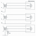
The totally floating alternative (upper)
Pro:
Pro:
Pro:
The totally floating alternative (upper)
Pro:
- Touching one secondary lead and no virtual ground on lab desk will send hardly no current thru body.
- A loose lead in any coupled devise that touches the CT bonded virtual ground will lead back that way which is the lowest impedance route and not thru human body. Local fuse will blow.
- CT will provide a stable reference VS secondary leads
- Mains noice from L, N and PE will be limited by the isolation transformers interwinding shield.
- Touching one lead and virtual ground at the same time will send 115 V current thru human body.
- HF noice induced by lab environment will have a higher impedance route back to main earth ground. Most will convert to heat in the isolation transformer and radiate HF from that.
- Lab environment will float versus surroundings and main earth.
Pro:
- Touching one secondary lead will send hardly no current thru body. Even if touching ground (PE) with other hand.
- A loose lead in any coupled devise that touches PE bonded chassies will be routed that way and blow fuse.
- HF noice induced by lab environment will have a low impedance route back to earth away from the lab environment.
- Mains noice on the N lead will couple thru PE and will be present in lab environment
- Lab environment will float versus surroundings and main earth.
Pro:
- A loose lead in any coupled devise that touches PE bonded chassies will be routed that way and blow fuse.
- Mains PE noice will be limited by large inductor.
- Lab environment will have a stable ground and will not float.
- HF noice induced by lab environment will have a fairly low impedance route back to earth away from the lab environment. Some will turn to heat in inductor and some will turn to heat in the soil far away.
- Lab feed will be balanced which can be a pro for some equipment.
- Touching one lead will send 115 V thru human body.
- Mains PE noice can find its way thru inductor to lab ground
- Mains PE noice will radiate from inductor.
Attachments
My (bad) intuition tells me I want none of those diagrams.
Instead top diagram without the centre tap and just use a fused two wire power feed.
And an MCB+RCCB on the mains feed into the isolating transformer in case it ever becomes faulty.
But, I am open to hearing what the experts are prepared to tell us.
In the absence of any contributing experts, the NEC clause rules. That forces me/us into the middle diagram. Does anyone disagree?
Last edited:
My (bad) intuition tells me I want none of those diagrams.
Instead top diagram without the centre tap and just use a fused two wire power feed.
Are you then including feed to lab gear like scopes and generators and not only the DUT? Then I dont undestand why you dont want to include a grounding of some sort.
the isolated power to everything except the scope.
The scope probe ground connection to PE must never be defeated.
Or maybe that rule only applies when isolated power is not available.
WE need some, or even one expert here !
If you have a virtual PE on the test bench, then you bring back the risk of a one hand electric shock.
The whole point of isolated power is the removal of the risk of one hand electric shock.
The scope probe ground connection to PE must never be defeated.
Or maybe that rule only applies when isolated power is not available.
WE need some, or even one expert here !
remember post8Then I dont undestand why you dont want to include a grounding of some sort.
Mains power is dangerous for three reasons.
It is highish voltage
It is high current.
It needs ONLY one hand on a Live part to take current back to Earth.
It's this last that makes it VERY DANGEROUS !
By using an isolation transformer you change that last problem.
With an isolation transformer that has the output NOT connected to Earth, one needs TWO hands connected across the highish voltage for current to flow.
That is the fundamental difference between Mains power and isolated power.
If you have a virtual PE on the test bench, then you bring back the risk of a one hand electric shock.
The whole point of isolated power is the removal of the risk of one hand electric shock.
Last edited:
If you have a virtual PE on the test bench, then you bring back the risk of a one hand electric shock.
The whole point of isolated power is the removal of the risk of one hand electric shock.
No there you are wrong imho. You need to touch both virtual ground and a lead or the two leads to get current thru body in the upper alternative. Everything floats. Panta rei😉
Yes, the same risk as sitting at the workbench and working with mains direct.
An inadvertant lean/rest/touch to virtual ground while holding/touching a Live component.
An inadvertant lean/rest/touch to virtual ground while holding/touching a Live component.
Yes, the same risk as sitting at the workbench and working with mains direct.
An inadvertant lean/rest/touch to virtual ground while holding/touching a Live component.
Not at all the same risk.
Mains direct:
- Touch one wire: 230 V at max mains fuse amperage thru body
- Touch two wires:230 V at max mains fuse amperage thru body
- Touch one wire and no metal on the lab environment: Almost no current thru body.
- Touch one wire and metal on the lab environment: 115 V limited to the amperage of the trafo.
- Touch two cables: 230 V limited to the amperage of the trafo.
The NEC is very clear, and does not permit floating systems. 250.20(B)(1) requires it. Balanced power systems are also prohibited except in commercial applications.
There are a number of individuals on this forum that insist NEC does not apply to them, nor does it apply when you creatively call your garage bench a "laboratory". That is certainly their option, and it is pointless to argue the point with them.
For your purpose, the correct, proper, and safest method that is compliant with all national and local codes is to bond one side of the winding (now becomes the neutral) when using a so-called isolation transformer. Interested in making measurements? Buy a differential probe.
All these floating suggestions in the interest of safety come from those who refuse to spend the money on a differential probe.
NEC is the rule book for ELECTRICIANS for wiring buildings in NA. NEC applies to permanent installations/ facilities not "appliances" / equipment purpose built for specific lab test stations that are used by electronic technicians with safety training.
don't let an electrician dictate your test equipment specifications!
NOTE the title of the thread reads for LAB BENCH
don't let an electrician dictate your test equipment specifications!
NOTE the title of the thread reads for LAB BENCH
Last edited:
Those so-called appliances have approvals such as UL listings that shows they are built correctly for the purpose. Get a UL listing and we'll talk.
My guess is you suggest the OP not bother to buy a diff probe.
Might want to also call up Tektronix about how they feel about you plugging their scope into a floating system. Perhaps call Asus and see how they feel about using their computer in a similar manner.
My guess is you suggest the OP not bother to buy a diff probe.
Might want to also call up Tektronix about how they feel about you plugging their scope into a floating system. Perhaps call Asus and see how they feel about using their computer in a similar manner.
Last edited:
Clip the probe ground to the floating test point and the PE will bring the floating test point down to "Earth" potential by discharging the capacitance in the floating system.
Now attach the measuring probe.
Why would Tektronix want to ban that process?
Now attach the measuring probe.
Why would Tektronix want to ban that process?
Hope the link works, but it's very easy to find with Google.
There really is no argument to make. It's an obvious solution, but for whatever reason people think isolation transformers are the cure-all.
https://www.google.com/url?sa=t&rct..._1.pdf&usg=AFQjCNGRpMcmocglLXM8LQQQydiI5CKiPA
There really is no argument to make. It's an obvious solution, but for whatever reason people think isolation transformers are the cure-all.
https://www.google.com/url?sa=t&rct..._1.pdf&usg=AFQjCNGRpMcmocglLXM8LQQQydiI5CKiPA
some do some don't. I have personally obtained UL LISTING, I was the lead designer for SMPS built for both Tektronix and Intel. I still see the Intel unit for sale on Ebay. some of the tests for checking internal things had to be floating, the chassis was groundedThose so-called appliances have approvals such as UL listings that shows they are built correctly for the purpose. Get a UL listing and we'll talk..
that was your suggestion, I don't know what the OP is testing so I wont dictate one for his set up.My guess is you suggest the OP not bother to buy a diff probe.
NO I NEVER once suggested floating the test equipment! every isolation transformer has its purpose.Might want to also call up Tektronix about how they feel about you plugging their scope into a floating system. Perhaps call Asus and see how they feel about using their computer in a similar manner.
you seem to be mixing things up between equipment designed to be sold for purpose and a test station.
"floating" is for the device under test only and just for trouble shooting, I am not suggesting floating a bunch of test gear.
Last edited:
On very good grounds then since NEC applies only to United States and even there is not federal law but an adoptable standard.There are a number of individuals on this forum that insist NEC does not apply to them, nor does it apply when you creatively call your garage bench a "laboratory". That is certainly their option, and it is pointless to argue the point with them.
First and foremost I would like the discussions to be about pros and cons regarding our cause which as said is a lab bench which is somewhat safe and in a good way gives us our disturbance free current need there.
most of my mains powered test instruments are floating. They have isolating transformers inside..............
"floating" is for the device under test only and just for trouble shooting, I am not suggesting floating a bunch of test gear.
All my portable/battery powered test instruments are floating.
The exception is the scope and no one has replied to the question whether it should remain PE connected or floated on the isolated supply.
the isolated power to everything except the scope.
The scope probe ground connection to PE must never be defeated.
Or maybe that rule only applies when isolated power is not available.
WE need some, or even one expert here !
- Status
- Not open for further replies.
- Home
- Design & Build
- Equipment & Tools
- Isolation tranformer to lab bench