Did you build that one? What a beauty!
I've long been a fan of the Verdier turntables, this looks like it's in the same family. And it's DIY? Crazy?
It is my "project" but I can't take much credit for it. It started with Teres and the bearing from Chris .Than I heard comparison between his wooden platter and acrylic and as about the only one in the room I preferred warmer sound of plastic platter. I stumbled on Galibier pages and exchanged few emails with Thom and since it was quite a few years ago he has right not to remember. Basically I was going to follow Serac design since I'm not an engineer nor do I poses the virtue of scientific rigor and logical pursuit.I read on Galibier pages that that type of bearing seem to "like" contact with plastic . I was little encouraged by Chris Brady who privately admitted that his success and result with Teres sound is in part accidental and it's really hard to predict the outcome. A few years ago Vistek Inc. anti-vibration pro microscope base appeared for sale on those boards and my friend had bunch of gun metal rods to sell as well. I looked at the base ,thought about rods and I recalled Kuzma Stabi turntable so I bought the rods , the base and found old retired machinist in town with old but nicely kept shop in the garage. Mark Kelly speed controller from 2006 GB , Basis precision belt and Mr Marek Stojek string suspended 12" tonearm add to the package. I made many "designing"
mistakes , some of them still need another corrections , all machinists have their own "ideas" how the things should be done even if you respectfully disagree and ask them to just do what you ask for . At the end I like the table . It is immune to acoustic feedback and sounds full and spacious sort of old Sondek LP12 way (which is a fine , musical table IMHO midbass hump and all the warts )with better bass and scale. Also I like it as an object occupying my living space. The fact that I struggled to make it happen surely corrupts my judgment regarding the objective sound of that thing.From the perspective it would be easier to acquire second hand Galibier or Verdier tables which I also admire. That's the DIY reality 😱
Last edited:
Lynn, would you explain the purpose of the resistors between the current-sources and plates of the driver tubes in the Karna Kay and Symmetric Reichert? What current-sources do you plan to use?
Lynn, would you explain the purpose of the resistors between the current-sources and plates of the driver tubes in the Karna Kay and Symmetric Reichert? What current-sources do you plan to use?
Current sources are not perfect. In a direct A/B comparison at Gary Pimm's place, he switched between different types of current source (used as dynamic plate loads in a SE circuit).
I was a little surprised; the generic two-transistor CS made the linestage sound like a mid-fi transistor circuit, despite the fact that all it was doing was providing a dynamic load to an otherwise all-tube circuit. Switching to the final version of Gary's current source made the circuit revert to the expected tube sound, just with more dynamic range and quietness. We repeated the test in several formats, and the most revealing was a A/B/A format. When you acclimate to a given sound, changes away from, and a return to, are the most audible, and reveal the character of the difference most strongly.
As for the coloration, Gary's best guess, along with mine, is the conventional bipolar transistor current source has a significant amount of nonlinear capacitance, and it is significant enough to add a distinct and noticeable grain, edginess, and 2-dimensionality to an otherwise good tube circuit. I found the added coloration unacceptable; any type of conventional resistor plate loading sounded better and more natural. By contrast, Gary's current source sounded like resistor loading, just with more dynamic sound and quieter backgrounds.
Gary Pimm's current source takes a brute-force approach to minimizing unwanted capacitance by using cascoded MOSFETs and careful layout on the circuit board, which reduces capacitance to less than 0.1uF (which is very difficult to measure, by the way). The cascoded high-voltage MOSFETs have the additional advantage of extremely high voltage standoff; Gary exposed the current-source to more than 1000 volts, and it survived with no change in measured parameters or sonics.
The "transistor" or MOSFET coloration on Gary's current-source is very low, but I'm not sure it is zero. The purpose of the resistor between the current source and the plate of the tube is to further isolate this small capacitance from the audio circuit. If the circuit used audio-grade choke or inductor instead of a current source, there would be a resistor in the same location for the same reason: to isolate unwanted stray capacitance from the audio circuit.
Last edited:
…
The purpose of the resistor between the current source and the plate of the tube is to further isolate this small capacitance from the audio circuit. If the circuit used audio-grade choke or inductor instead of a current source, there would be a resistor in the same location for the same reason: to isolate unwanted stray capacitance from the audio circuit.
Yet in the latest schematic of Karna Kay, the second stage of the driver is fed by a choke, without any series resistor following it. So I wonder. Or is the series resistor to the choke applicable only when it doesn't feed interstage transformer?
In general, transformers and iron cored products "like" low impedances. If we feed one transformer with zero impedance we have zero THD in bass. HF is another story, but we still need low impedance in order to overcome the parasitic capacitance. If we put a resistor in series with the transformer, we increase drive impedance and impair the response, distortion or both. And the trafo needs to receive 100% of driver signal since the power stage is connected to secondary of the same. So low impedance triodes is a must for driving trafos.
But in my view, some chokes have margin to add series resistance, since chokes only provide DC, normally have more inductance and the signal passes to the next stage through capacitor. Patrick Turner, from Turner Audio for example, uses some resistace in series with chokes for equalize the out-of-band response and maintain stability since he uses feedback in most projects.
I always use this resistor in series with chokes or CCS; my impression and experience about that is like the Linn Olson last post description (specially about bipolar CCS).
Last edited:
One more thing: probably is the 5H/120mA local PSU decoupling choke the question... This is decoupled with an 80µF/400V cap and is not directly coupled to triodes/signal. Even so, in my personal projects/preference I add some resistor for additional HF supression and lower the Q from LC filter (see 6. Resonance in CLC filters in audiofilterchokes ).
Thom
Yes , I'm probably a lousy builder. The amps were quiet , measured (static operating points ) exactly to specs. Parts selection followed Herb choices since he stated that if one will substitute beyond his recommendations it won't be F&B anymore sort of things . I had 1.5 H 16 Ohm chokes and 300VA power trans , Cerafines PSU and black gates and jensens , tantalums. Anyway I made clone of Yamamoto 08 with Bud's level one Opts and it also sounded like a distant cousin from the real thing. There are so many considerations when building.
Regarding the turntable I should have specified that it was not your PVC platter although I bought it from your Aussie customer who upgraded to one of your high spec platters (stelvio or gavia) and the bearing I got from Chris Brady. I don't want to build any more DIY tables....ever😀
Quickly, as I don't want to derail this thread further ... It sounds as if you are on the threshold of taking the next step in your efforts, but at the same time, this could require a lot of suffering, and many of us are too smart to undergo this much torture 😱 Layout techniques can border on black magic, which is the main reason Henry of Redplate Amps (the guitar amps) could care less if his schematics are made public.
Putting it all together with a turntable design requires a similar level of suffering, and in this case, the machining of all too many "door stops" - at too high of a price.
We're just now learning what to measure, along with the effects of the intangibles of layout (in amplifiers) or material combinations (turntables).
Back to our regularly scheduled programming ...
Cheers,
Thom
Yet in the latest schematic of Karna Kay, the second stage of the driver is fed by a choke, without any series resistor following it. So I wonder. Or is the series resistor to the choke applicable only when it doesn't feed interstage transformer?
Not sure about this reference. Going by memory, the center-tap of the interstage is connected to a choke shunted by a power-supply cap going to ground. The choke probably has 30 to 50 pF of winding-to-case capacitance, but this is in parallel with the much larger power-supply cap. The characteristics of the PS cap will dominate, since it is hundreds of times larger.
As a minor point, the two wires coming out of the choke will not have similar capacitances. Ideally, the choke should be measured with a precision LCR meter, and the higher-capacitance side reserved for the B+ side of the circuit. Similarly, the AC primary wires coming out of the power transformer should be measured, and the higher capacitance wire should be reserved for the neutral side of the incoming AC power. This minimizes ground loops with other parts of the system.
I try to keep track of stray capacitances and also look at the flow of audio-frequency currents going through the amplifier stages and in the driver/amplifier interface. Since current always flows in a loop, that means that components in the so-called "ground" side of the circuit also have an effect on potential coloration.
It seems minor, but I wire the speaker crossover with a star-ground topology, keeping the loop area as small as possible (while minimizing inductor interaction). In the amplifier, it is very important to minimize both emission from the rectifier section (by keeping loop area small) and susceptance in the input section (by twisting wires going into the grids).
Last edited:
By the way, the postings by Zigzagflux and Steve Creswell in the Tube/Valve forum are worthy of very close reading. Straight pentode with precise screen regulation and local feedback in a fully balanced circuit can give all-triode amplifiers a run for their money ... and at far lower cost.
Gary Pimm's current source takes a brute-force approach to minimizing unwanted capacitance by using cascoded MOSFETs and careful layout on the circuit board, which reduces capacitance to less than 0.1uF (which is very difficult to measure, by the way).
The shunt capacitance of Gary Pimm's current sources is even lower than that, actually. From his website:
Fixture limit: .009 pf
Rev. 5: .023 pf
Rev. 4: .932 pf
Rev. 3: 4.682 pf
Self bias w/pentode: .04 pf
Self bias: .08 pf
Battery bias: .08 pf
2G test resistor: .159 pf
Gary Dahl
Well, it all depends on the spectral characteristics. One of the unusual aspects of the 45 and 300B is extremely low high-order spectral content; it's almost entirely 2nd harmonic, about 20 to 30 dB lower 3rd harmonic, and 4th and higher vanishing into the noise around -120 dB. Unfortunately, the 2A3 isn't quite as good in terms of high-order harmonics.
As a group, the IDHT's are good, but nowhere close to what DHT's can do. The 6SN7, and the direct predecessors like the 6J5, 6P5, 6C5, etc. are in a special low-distortion group (looking at the upper harmonics). The performance of the 5687/7044/7119 family is better than the 12AU7 and 6DJ8, but that isn't saying much.
Lynn, I keep on forgetting to ask. Have you considered the EML-20A, EML-20B or EML-30A tubes? Would one of them not be a good modern substitute?
Enjoy,
Deon
MyLynn, I keep on forgetting to ask. Have you considered the EML-20A, EML-20B or EML-30A tubes? Would one of them not be a good modern substitute?
Enjoy,
Deon
 : I think they are promising 🙂 but the rp is higher than 45 (for example) and very expensive 😱
 ...
...---also awaiting the Linn Olson opinion---
Lynn, I keep on forgetting to ask. Have you considered the EML-20A, EML-20B or EML-30A tubes? Would one of them not be a good modern substitute?
Enjoy,
Deon
Wonderful ... and also frighteningly expensive if you're talking about 4 of them. The last time I messed with them, they were also kind of microphonic, which I hope has been cured by now.
If the Chinese meshplate 2A3's have low distortion from 5th harmonic upward (have not measured them), they would be a sensible choice, since they are substantially less expensive than Chinese 300B's (which are pretty good). Some of the old-stock tubes that have been mentioned look interesting as well.
The goal is less high-order distortion than general-purpose IDHT's, and lower Rp as well ... basically, a very clean 1~2 watt amplifier that drives the 300B pair. Yes, the same power range as a headphone amp, but with 120V rms drive capability.
Last edited:
Hey- thanks so much for tell us about it! Your story offers some nice insight and lets us know what is behind the project and the builder. So often we just don't have a clue of all the work, the decisions, the mistakes, the paths taken or not taken. Always good to learn about that part, too.It is my "project" but I can't take much credit for it. It started with Teres and the bearing from Chris

Why so few measurements and details? HERE'S MY OWN!
Hi all,
one thing that I noticed in this wonderfully informative and thought-provoking thread is a rather puzzling dearth of actual complete build examples, supported by actual measurements.
In an attempt to buck that trend, I hereby offer my own design for scrutiny, which, even if not fully "beyond the Ariel", still by and large shares the same fundamental principles.
1) DRIVER SELECTION
WOOFER: Fostex FW405N (FW405N | FOSTEX)
This is a modern woofer of recent design, with a hybrid cellulose+carbon fibre cone and a newly developed aluminum die-cast frame based on FEA. Magnet is ferrite, and sensitivity is medium-high at 92.5 dB/W(m) (declared) / 94 dB/W(m) (calculated based on the T-S parameters).
Two features that attracted me were:
(i) its medium-low overall damping (Fs/Qts = 60), which allows to use an overdamped bass-reflex box characterized by very low Group Delay (Vb = 2 * VAS * Qts) and still get an F-3 = 40 Hz;
(ii) its very low mechanical damping (Fs/Qms = 4.0), which in my experience is a recipe for excellent low-level detail retrieval.
By way of comparison, this is roughly the same mechanical damping as that of the GPA 416 (Fs/Qms = 3.4) and the TAD TL-1601a (Fs/Qms = 4.1), and HALF of that of the JBL 2226H (Fs/Qms = 8.0).
COMPRESSION DRIVER: Fostex D1400 (D1400 | FOSTEX)
This is an 'old style' 1" driver with a Ti-alloy diaphragm, half-roll surround and massive AlNiCo magnet. Its internal structure is basically a copy of the TAD TD-2001, with a large back-chamber and an internal conical throat characterized by a low cut-off frequency of 400Hz. These characteristics allow it to perform very well down to much lower frequencies than most modern 1" drivers (at domestic levels, of course, and when coupled with a suitable horn). In fact, its minimum recommended crossover is a low 750Hz (presumably when used with Fostex's own larger H300 horn).
HORN: Fostex H400 (H300/H400 | FOSTEX)
This is where I decided to go 'all Fostex' and try my hand at a 'classic' radial exponential horn (Fc = 455Hz)... but with a few caveats! In fact, this horn differs from e.g. the 'über-classic" Altec 811 in two important ways:
(i) it is carved out of a block of dense high-grade sugar maple plywood (density = 0.67 kg/dm3). This gives it excellent self-damping and prevents the notorious 'ringing' of the classic metal horns.
(ii) its (cast aluminium) throat adapter is perfectly matched to the driver's internal 400Hz flare rate, and operates an extremely smooth transition from the driver's 1" (25.4mm) circular throat to the horn's 35x35mm square throat.
Of course, all this does not change the fact that this is still a 'flawed' design in the other classical ways (calculated based on Webster's equation assuming cylindrical wavefronts, producing some diffraction at the adapter/horn throat interface and at the horn mouth, etc.). But my hope in selecting it was that the two positive points listed above would go a long way in minimizing any unwanted 'horn honk'...
Super-TWEETER: Fostex T925A (T925A | FOSTEX)
A classic 'bullet' tweeter, with an aluminium ring diaphragm and large AlNiCo magnet.
2) PASSIVE CROSSOVER:
For the Woofer-Mid crossover, I got inspiration from the design used by Pioneer in their TAD/Exclusive monitors (EXCLUSIVE model2402), and later reprised by Shozo Kinoshita in his Rey Audio monitors (RM Monitor), and I designed an asymmetrical 6th-order low pass / 2nd order high pass.
The crossover frequency was chosen to be 850 Hz, so as to:
(i) match the horizontal directivity of the Woofer to that of the radial horn (110 degrees);
(ii) stay approx. one octave above the horn's cut-off.
When both the Woofer and Mid are connected with positive polarity and the Mid is phisically set back so as to create a suitable offset between the two acoustic centres, this crossover results in the emissions of both drivers to be in phase over a relatively wide frequency range around the crossover frequency [see actual measurements in FIGURE 1].
This type of crossover is handy in several ways:
(i) the front-to-back offset allows the convenient positioning of the horn-loaded mid atop the Woofer box without requiring any form of delay (digital or otherwise);
(ii) the same offset also happily results in the two impulse responses to be almost perfectly 'time aligned', i.e. both traces leave the horizontal line simultaneously [see IR measurements in FIGURE 2];
(iii) the 6th-order low pass effectively does away with any unwanted resonances at the top of the woofer's operating range.
For the second crossover between Mid and super-Tweeter, I opted for a symmetrical 2nd-order Buttwerworth at ~7.5 kHz, which gives a Constant Power response.
The super-Tweeter is not time-aligned because:
(i) at such high frequencies, the human auditory system's sensitivity to phase is reduced;
(ii) the resulting comb filtering pattern is essentially inaudible since the narrow notches are within the ERB (https://en.wikipedia.org/wiki/Equivalent_rectangular_bandwidth);
(iii) having an intentionally misaligned constant power crossover at such high frequencies results in a smoothed summed response that is essentially invariant over a +/- 30 degree listening angle, since any additional misalignment introduced by moving the head laterally is swamped by the the >360 degree original misalignment.
I realize this design choice may be somewhat controversial, but IMO while it looks bad in a simulation, it actually sounds better than any other option (i.e. better than just going 2 way and making do with the compression driver's response over the top octave, and better than trying to obtain a time-aligned all-pass crossover between the mid and the supertweeter, and then living with the 'hole' in the summed response that is produced off axis).
From a practical point of view, the complete crossover was built using quality parts (Mundorf coils and Jantzen MKP capacitors), and housed in two external wooden boxes [FIGURE 3].
The woofer low-pass section [FIGURE 4] uses a semi-balanced topology to reduce crosstalk with the mid and tweeter sections [FIGURE 5].
Both the compression driver and the super-tweeter are attenuated using variable units by Fostex (R80B/R82B/R100T | FOSTEX), respectively the transformer-based R-100T for the CD and the R-80B potentiometer for the sTw.
The resulting system impedance plot is shown in [FIGURE 6].
The final system's measured in-room response (unequalized and not corrected in any other way) is shown in [FIGURE 7], with superimposed the well-known Bruel & Kjaer 'target' function, as well as a +/- 3 dB tolerance band.
And to conclude, a picture of the full system taken from the listening spot [FIGURE 8].
C&C welcome!
Cheers,
Marco
Attachments
-
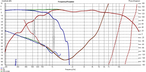 FIGURE 1 (Wf+Mid phase match).png30.6 KB · Views: 721
 -
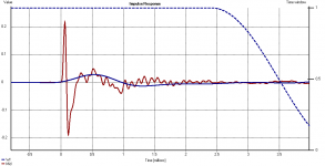 FIGURE 2 (Wf+Mid IR).png22.2 KB · Views: 729
 -
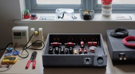 FIGURE 3 (crossover).jpg648.7 KB · Views: 756
 -
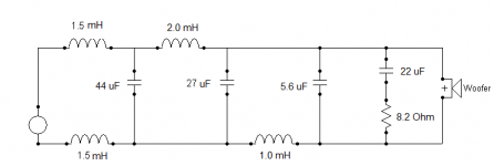 FIGURE 4 (Wf schematic).png5.6 KB · Views: 709
 -
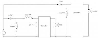 FIGURE 5 (Mid-Tw schematic).png7.4 KB · Views: 699
 -
![FIGURE 6 [system Z].png](/community/data/attachments/452/452306-e4e1f06e4e98e4ea13f4cfccdadf35c6.jpg?hash=5OHwbk6Y5O) FIGURE 6 [system Z].png27.8 KB · Views: 261
FIGURE 6 [system Z].png27.8 KB · Views: 261 -
![FIGURE 7 [inroom & B&K target].png](/community/data/attachments/452/452314-b826afbacd148cc97ff7b0cef99001fd.jpg?hash=uCavus0UjM) FIGURE 7 [inroom & B&K target].png33.9 KB · Views: 251
FIGURE 7 [inroom & B&K target].png33.9 KB · Views: 251 -
![FIGURE 8 [full system (annotated)].JPG](/community/data/attachments/452/452326-3e8afc5ae6a68b84be12350a2405dd12.jpg?hash=Por8Wuami4) FIGURE 8 [full system (annotated)].JPG708 KB · Views: 398
FIGURE 8 [full system (annotated)].JPG708 KB · Views: 398
Very nice crossover work Marco!
Only the range from 850 Hz to 1.6 kHz looks like it needs some suppression.
Only the range from 850 Hz to 1.6 kHz looks like it needs some suppression.
What program did you use to plot the polar map?
I used Matlab for all the plotting and crossover simulation.
You can do that if you want, but some time ago I offered to run polar maps on anyone's data and if there was enough interest to make my software available. I will hold to that offer, but alas, almost no one has taken me up on it. There is a whole thread on this somewhere.
PS. Klippel recently announced his use of a technique that is virtually identical to what I have been doing for almost a decade now.
Earl,
So are you offering your software for use? What type of files or information do you need to make it work? Would the MLS files from Clio work with your software? I'm interested to see what you have. At the same time what is the real advantage or your software besides having a different type of display over an older polar plot besides the nice colors!
So are you offering your software for use? What type of files or information do you need to make it work? Would the MLS files from Clio work with your software? I'm interested to see what you have. At the same time what is the real advantage or your software besides having a different type of display over an older polar plot besides the nice colors!
My software uses HolmImpulse data files. This makes the most sense to me because this software is free. I didn't want to pick a software package that was not free for obvious reasons.
There is a white paper on my web site that explains all the details of making the measurements. Initially one will have to send me the raw data and I will post the results.
At some point my intent is to make the actual plotting software available as an app, but I am reluctant to do that initially. I don't want to release it until I can support it as I know how many bugs show up in the field when you let anyone use the app (been there done that!!) I have mostly retired now so I can consider supporting some software like this - a couple of years ago this would have been impossible.
I believe that it is critical to have some common basis of comparison of polar maps. One needs these for a valid look at any loudspeaker (single axial curves being almost useless) and polar responses can be manipulated in a lot of ways. My techniques are now becoming quite standard (to wit the Klippel techniques that I mentioned before) so there shouldn't be any claims that my software is manipulating the data in invalid ways. Looking at all the pros and cons of different design approaches in a common format that is know to be valid is essential to one deciding how to proceed. All this "sounds good to me stuff" just doesn't cut it anymore - gladly (hopefully!?) we have moved beyond that phase.
Last edited:
- Home
- Loudspeakers
- Multi-Way
- Beyond the Ariel