[Solved]Martin Logan Ascent i panel not working
****Problem Solved, See End of Thread****
I need a little help troubleshooting. I bought this pair, knowing one panel was not working. I opened the box up this morning, and found "8894 Upgraded to 'i' and QC". Explains why the speaker is labeled as Ascent, but has the blue LED of the i model.
On to the issue. I checked continuity on all of the panel connections, followed back to the terminal block, all good. I'm trying to check voltages in the circuit, but I'm not quite sure what I should be testing.
The weird thing is, when I check voltage with my digital meter between the red and black wires going to the panel it begins to play loud. I assume my meter is charging the panel.
Can someone help me with test points and voltages so I can nail down the issue? My thought is the transformer, but I'd like to be a little more educated on making that determination.
Thanks in advance!
Last edited:
go here an search..............tweeks an diy pages.......I work on logans....I have had 3-4 pr of the Asents -I....an others....but start here.....good luck
Main Discussion Forum
Main Discussion Forum
I appreciate the suggestion. I'm a member and have searched both forums for what I'm asking and haven't found an answer for what pins to test and voltages to expect. Just a hint would really help.
Well if one speakers panel is working.......an one is not....take the working back plate off.....the pic is a back plate ... put it on the other no-working side....if that panel works you now know it the bias?.....if the black or blue wire are still on the panel?..........pulling the panel out off the rubber side peaces is a pain in my ***............but can be done.
The bias feed is the red wire an center tap of the transfourmer.....it the yello wire.....forget cking the blue an back....theres nothing to ck ....as long as there still on the panels.?.....panels slipages is one thing that kills panel output....last pr I got looket new but the panel had slip down an pull the black wire off the panels....I put it back on the panel....all work fine ....
I only pay about $100 a pr for any of these type of no-working ML....why....if its a dead panels... new panels are about $2k .....
so if I pay to much....an the panels out....the speakers are just good for parts.....
Now as for cking high V bias.....it about 2-3k v....you well need a High Voltage Meter .....most meter diyer have are only good up to 1kv.....you can kill the bias an meter.... with the lower v meter.....but if it the bias...new bias boards were $50ea.....if both panels work a new bias board would be the way to go good luck
Attachments
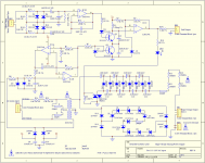
![IMG_1180_V[1].jpg](/community/data/attachments/440/440634-4a8c5c51b0fa0cf3ac8161cca134ac20.jpg?hash=SoxcUbD6DP)
Last edited:
Thank you for the schematic, I already swapped panels and both panels are good. There's definitely not enough v getting to the panel, so I'm digging into it now. I do have a high voltage tester, and a scope/curve tracer. I'll probably check all components and compare curves part by part. Looks like it may just be the transformer.

new bias boards were $50ea.......key word is....were!.....boy thay lost there minds...but money makes A.....some thing go round...
ML...would just like most to put there speakers..in the junk... after 5 years....an run down an get a new pr from them..so thay can make some real $$..............
When people call an say my $10k speakers not working.. an here the cost...like $2500 for new panels.........thay go right on CL......I allways say if you like ML buy new.... an sale in 3-4 years.....
Any ML panel over 5-7 years.... is only putting out 60-70%...... but most cant tell.
Now I got line on a pr of Quest Z.....the guy cant let go.... yet.....$50. for the pr....or fire wood.. it his call..............Magnepans are the same....tweeter stops working...most well not ship....I have a pr of MG2.5r playing now....I paid $35......bass wire buzz ..ezey fix
now it ezer to see.....why I only pay $100. tops... for any used ML...... over 5years old....people say but that look like new!..... right parts maybe...
bias is bias...you can diy a bias for your Acents....look on the web....3.7kv is what you need...............good luck
They came back with a better price after I choked a little, but it's still high considering I think I tracked it down to a bad diode. I'm hoping I can swap that and get the v back. I got these for cheap, so if I can get them working I'll have a good pair of speakers. Already fixed the woofer circuit on the other speaker, and upgraded the caps. Going to put the same caps in the other side when I get the voltage back. Thanks again for all your help. Also looking at your other posts I want to do some mods on my SL3's. They're my favorite pair of ML so far, but I'd like to make them better.
Wow!Opened up the WORKING speaker, and found this.
Looks like the woofer level control switch got hot enough to set itself on fire. The resistance of the switch contacts must have increased from pitting...wonder if the switch was designed for switching at rated current. The manual doesn't specifically warn against operating the switch while listening to music.
In any case, shouldn't be too tough to fix by replacing the 2 capacitors and bypassing the switch.
Did you make it clear that you only needed the PC board with the bias supply and limiter on it? $394 sounds like they quoted you a price for the whole interface(ie including transformer and crossover). I purchased a similar bias board last year for $65 shipped.Tyu, where are bias boards $50? ML just quoted $394 with shipping for 1.
Have you determined what is wrong with the bias supply? If it is just the transformer you can likely get those for < $20.
http://www.diyaudio.com/forums/plan...ittent-bias-supply-problem-2.html#post3085792
If you haven't started troubleshooting, you could start by measuring the voltage across each of the 8 caps in the bias supply with a standard 10Meg input impedance DVM. All should be in the neighborhood of 600 Volts DC except the first one will be about 300 Volts DC.
The auto bias supply portion of the circuit looks to be very similar to the SL3, so I attached the schematic for your reference.
Attachments
Last edited:
Bolserst- I actually replaced the switch and tested the resistors/coils around it. Everything survived, aside from the obvious carnage. It's all back together now with better caps, and working.
I love my SL3's, but the bass is much more pronounced out of the Ascent i aluminum driver. I saw somewhere that there is a good aluminum replacement for the SL3 from scanspeak, but it's hard to find.
I love my SL3's, but the bass is much more pronounced out of the Ascent i aluminum driver. I saw somewhere that there is a good aluminum replacement for the SL3 from scanspeak, but it's hard to find.

I can't find my HV probe, so I ordered a 1gig resistor to us for testing. Should be here tomorrow so I can find the voltage drop. So far I've just gone over components with a curve tracer. A couple of diodes LOOK out of spec, but that doesn't always mean anything with a ct.
The 1Gig resistor is certainly needed to measure the output of the whole voltage multiplier.
But, as I mentioned, you can measure the DC voltage across each of the individual capacitors in the multiplier with just the DVM.
Alternatively, you can measure the AC voltage output from the transformer feeding the multiplier. It should be in the 240Vac to 270Vac range depending how you DVM deals with computing RMS voltage for slightly non-sinusoidal waveforms. The power supply uses a string of zeners to clamp the peak voltage feeding the multiplier resulting in flat tops on the HV sine waves.
I was working and didn't read the rest of your post, thanks for the info! I may have some time this afternoon to play a little, I'll let you know if I find anything.
I checked the caps on the non-working bias supply board, got mixed low readings. First cap in line is hardly showing any v. After looking at the schematic, the last cap should be between 2-3kv as it feeds directly out to the panel. Checked voltages on my good supply, and the v did indeed climb at each cap, all the way to 2.3kv at the output of C19.
Looks like there is no v getting to the ladder to begin with.
Looks like there is no v getting to the ladder to begin with.
Sounds nuts...an I know you well get the two bias boards working....but I have ran both panels off one bias board.....works fine..but the high v wires running from speaker to speaker is a pain......but all well work fine...an you can see if the panel output is the same.....it well suck if you do all this an end up with less output from one panel than the other.........been there done that.......justsaying
SL3s...there bias boards are much better..an sound better.....than these off the shelf ...type with almost no room to work.......good luck
SL3s...there bias boards are much better..an sound better.....than these off the shelf ...type with almost no room to work.......good luck
Where does v turn from ac to DC on this board? I get 247vac from the transformer, same after first cap on the non working board. The working board is giving me 240vac from the transformer, 260vdc after the first cap.
Excellent troubleshooting. This may actually be good news! (ie potentially a cheap repair)Where does v turn from ac to DC on this board? I get 247vac from the transformer, same after first cap on the non working board. The working board is giving me 240vac from the transformer, 260vdc after the first cap.
If you are getting 247 Vac at the first capacitor, it means that either the first diode or the first capacitor are faulty.
This would be C13 or D15 in the SL3 schematic I posted...I'm not sure what your exact component numbers are.
Can you post a close-up pic of your PC board?
Does your DVM have a diode tester function?
If so, you can test the first diode in circuit. (with power removed obviously)
Last edited:
The caps and diodes in that section look good. I removed the board and found a hot spot around a couple of the Zeners, I don't have much experience with those.


- Home
- Loudspeakers
- Planars & Exotics
- Martin Logan Ascent i panel not working