Is anyone here familiar with the practice of putting back to back diodes across the inputs of bipolar op-amps? I read somewhere that it protects the input stages from excessive voltages that can over time degrade performance.
Gordon.
Gordon.
Anecdotal evidence that such diodes could be one of the reasons the 5532 has a somewhat variable reputation, particularly when used in DAC final stages where any high frequency hash and noise could cause non linear behaviour of the input stage.

I suspect discrete diodes will be very different in characteristic compared to fabricated diodes on the chip itself, specifically junction capacitance.
Thanks. Couldn't find anywhere to enter a search term but Bing brought it up instantly,
When good opamps go bad
When good opamps go bad
Yes, and since the voltage between the two inputs should ideally be zero, diodes have very little effect, except (a minor one) on the noise gain.I found the original article referring to this idea. It seems that it would only be used to protect the inputs of opamps being inappropriately used as comparator's.
It is true that delicate input transistors, super-beta in particular are susceptible to damage from reverse bias, even moderate. Unlike the punch-through of MOS transistors, the effect is more insidious: the part still works, but is degraded.
This practice of connecting protection diodes is invariably followed in transceivers that use single transducer for transmitting and receiving e.g. in an echo-sounder.
Gajanan Phadte
Gajanan Phadte
There is a very interesting report on bipolar transistor degradation by reverse VBE stress freely available from the NXP website:
http://www.nxp.com/wcm_documents/models/bipolar-models/mextram/bctm90koolen.pdf
In a nutshell: the hFE at low collector currents drops and the 1/f noise increases enormously.
If there is a chance that your op-amp will be driven into clipping or will see a large input signal while its supplies are off, then it makes sense to add these diodes if they aren't included internally already.
By the way, besides the NE5534 and the NE5532, the LT1028 also has internal protection (two anti-parallel diode-connected Darlington transistors), as have the OP-27 and OP-37.
Last edited:
"In a nutshell: the hFE at low collector currents drops and the 1/f noise increases enormously."
That's what happens for the 5532 when used in inverting mode (CD player), and the negative supply comes up first.
That's what happens for the 5532 when used in inverting mode (CD player), and the negative supply comes up first.
"In a nutshell: the hFE at low collector currents drops and the 1/f noise increases enormously."
That's what happens for the 5532 when used in inverting mode (CD player), and the negative supply comes up first.
Positive supply at 0 V or more or less floating?
I can imagine you get a far too high DC current into the positive signal input during start-up when the negative supply is up while the positive supply line is more or less floating. Interesting that they survive those conditions with performance degradation. I would expect them to either survive with no damage, or to get completely destroyed.
It turns the grounded input transistor into a zener diode.
After it is avalanched it will still work, but the gain can change and it becomes noisey. We had that problem in a design where I work.
After it is avalanched it will still work, but the gain can change and it becomes noisey. We had that problem in a design where I work.
It turns the grounded input transistor into a zener diode.
After it is avalanched it will still work, but the gain can change and it becomes noisey. We had that problem in a design where I work.
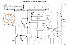
Strange... Looking at the schematic, I don't understand how having only a negative supply brings the input transistor into avalanche breakdown. I could understand it if, for example, the negative supply went very positive, positive enough to avalanche the emitter-base junctions of both the current source transistor and the input transistor.
Attachments
Strange things can happen with IC dies as you find parasitic parts 'appearing' and coming into play during non valid operating conditions. Maybe something like that could happen here.
looking at Electrostatic Headphone amps V protection seems important
a while ago I found a number of low C data line protection parts have interesting specs - at a fraction of the C of forward diodes, TVS or Zeners
onsemi CM1214A, ESD8472 are examples
some low noise BJT datasheets do warn that series R in unity feedback may be necessary to keep internal input protection clamping component current within abs max specs - often 10 mA
I would add a layer with the low C ESD devices where a few 100 Ohm doesn't destroy the noise performance and 10+ V "daylight" bandwidth input signal edges can't be avoided
If using glass external clamp diodes, it helps to paint them black (so they don't act like a photodiode).
Re: the 5532, a resistor may be placed in series with the grounded input (in inverting mode), but then you need a cap in parallel with the resistor too.
Re: the 5532, a resistor may be placed in series with the grounded input (in inverting mode), but then you need a cap in parallel with the resistor too.
"In a nutshell: the hFE at low collector currents drops and the 1/f noise increases enormously."
That's what happens for the 5532 when used in inverting mode (CD player), and the negative supply comes up first.
This actually happened to me recently, I think. I was experimenting with an amplifier with a x5000 gain using the two halves of a 5532. As I was working with a fairly messy breadboard layout the -ve supply got accidentally disconnected. The input noise of the 5532 and the DC offset both increased permenantly. I am assuming this is what happened, unless anyone else has a better theory?
Gordon.
- Status
- Not open for further replies.
- Home
- Amplifiers
- Solid State
- Back to back diodes at inputs of opamps