I also received the DAC and it seems to be working flawlessly. Thanks Quanghao!
It's to early to report on the sound quality but I think it will not disappoint from what I can already hear. So far only tested USB input and had no problems making it work with Amanero drivers via Jriver.
Build quality is great and I really like the display. One thing that worries me though is the fact that there is some serious electric signal running through the chassis. So strong that I can feel it when touching. Any ideas?
Hi baMarek,
Is the chassis earthed ? Maybe you should open up the DAC to check if it is earthed.
If not you should connect a 100 Ohm (5w) from the earth to your chassis.
Is the chassis earthed ? Maybe you should open up the DAC to check if it is earthed.
If not you should connect a 100 Ohm (5w) from the earth to your chassis.
Just received my dac which is playing nicely straight out of the box 🙂
However the battery for the remote is lacking. I just need Quanghao to confirm that the battery type is a CR2032 - 3V lithium?
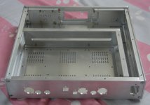
Also, I see from Alan’s pictures that the seperating walls isolating the psu section and the dac section are no longer there. What is the reason for this?
However the battery for the remote is lacking. I just need Quanghao to confirm that the battery type is a CR2032 - 3V lithium?
Also, I see from Alan’s pictures that the seperating walls isolating the psu section and the dac section are no longer there. What is the reason for this?
Attachments
Thanks Akltam! It was indeed earthing issue. I thought running 3 pin cable was enough but there is clearly something wrong with my installation. Moving to another wall socket fixed the problem.
Just received my dac which is playing nicely straight out of the box 🙂
However the battery for the remote is lacking. I just need Quanghao to confirm that the battery type is a CR2032 - 3V lithium?
Also, I see from Alan’s pictures that the seperating walls isolating the psu section and the dac section are no longer there. What is the reason for this?
yes, not need it!
i have all, but i not was use for this DAC.
thanks
Thanks Akltam! It was indeed earthing issue. I thought running 3 pin cable was enough but there is clearly something wrong with my installation. Moving to another wall socket fixed the problem.
what is your problem ??
please show me , thanks
quanghao
However the battery for the remote is lacking. I just need Quanghao to confirm that the battery type is a CR2032 - 3V lithium?
I just happened to have a CR2032 and I install it. It is working.
.... that the seperating walls isolating the psu section and the dac section are no longer there. What is the reason for this?....
I think the separating walls are designed in the first place to prevent interferance from the mains cable running around.
Whether they actually function effectively, I don't know. But it gives us the confident in the first place that little things like this has been taken care of.
It is a bit disappointed it has been omitted.
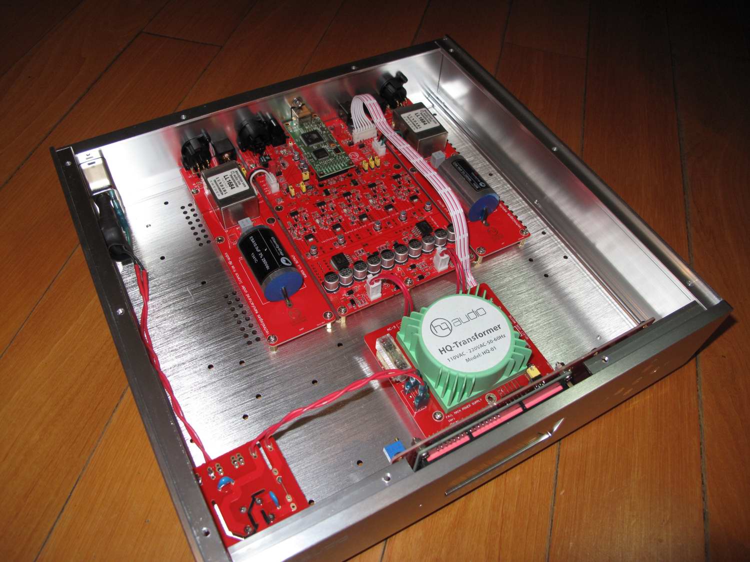
I received my dac wednesday your info was very helpful thank you kannan up to now everything seems fine thank you Quanghao.Received the DAC. One important information to note is input AC voltage. It was set to 220V AC. Since no clear information was present, I opened and changed the input voltage by removing the soldered jumper on the Transformer board/ re soldered new set of jumpers for 110V AC.
Hi Quanghao.
....be able to complete the payment I would like to know the shipping costs for Italy.
Grazie. Regards.
....be able to complete the payment I would like to know the shipping costs for Italy.
Grazie. Regards.
Hi Quanghao.
....be able to complete the payment I would like to know the shipping costs for Austria.
I have sent an email and a PM last week regarding final payment.
Regards.
Wolfgang Koenig
....be able to complete the payment I would like to know the shipping costs for Austria.
I have sent an email and a PM last week regarding final payment.
Regards.
Wolfgang Koenig
Modding the DAC
Hi,
Has anyone consider modding their DAC ?
First, I am not an Electronic Engineer. So don't take word for it.
I am thinking to add capacitors (electrolytic caps like 470uf and pair with a film cap like 0.1uf) to improve the power supply in the following points:
- at the point labeled 3.3V on the Amanero board.
- at the output of the 2 bigger LT1963 regulator (at multiple place where it starts to split into supplying the shunt regulators).
Any comments and suggestions to improve ?
(SMD components are getting too small for me to work on)😛

I just received my DAC yesterday and sadly will not be able to play with it until the weekend.
I snagged a pair of lightly used Jupiter Condenser Flat Stacked Beeswax caps on Audio Asylum last year to replace the ClarityCaps in the output stages. Not quite up to the standard of Erlend above but based on reviews they should add a nice laid back analogue character to the sound.
I'm going to let the base setup play in for at least a month or so first to see if I can identify any dicernable improvement when I install the Jupiters.
... received my DAC yesterday and sadly will not be able to play with it until the weekend...
Make sure it is the right power supply voltage for you. 😉
Cheers.
How do you check? Take the cover off and check the transformer wiring?
Make sure it is the right power supply voltage for you. 😉
Cheers.
How do you check? Take the cover off and check the transformer wiring?
See Thread 299. Yes, you have to take the cover off.
For those location that use 110V, you have to check if there is a jumper/wire soldered on 220V. If so, you have to remove that jumper/wire. And then you resolder the jumper on 110V. I think there are 2 of these jumpers.
Dear Quanghao and Kannan_s,
Please confirm how you connect the transformer to use 110V. 🙂
Capacitor missing?
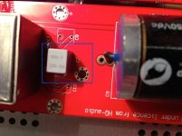
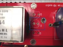
Examining the Lundahl output boards, I discovered a small grey Ero capacitor (C7) which is only present on one of the boards. The C3 spot is empty. Assuming the boards for each channel (L/R) should be identical, I’m a bit puzzled. Is this supposed to be so?
Examining the Lundahl output boards, I discovered a small grey Ero capacitor (C7) which is only present on one of the boards. The C3 spot is empty. Assuming the boards for each channel (L/R) should be identical, I’m a bit puzzled. Is this supposed to be so?
Attachments
- Status
- Not open for further replies.
- Home
- More Vendors...
- Quanghao Audio Design
- DAC-END R (ES9018) full assembled board - version 2 - group 2