Dear all,
looking for a new project with 300B, I thought to build an amp with an IT.
As a driver, I like to use a D3a (strapped to triode).
(I don't want to use the usual 5842 tube. I like to use the IT in 1:1 configuration)
Does anybody have a proven circuit which I can take as basis?
I built once the 6SN7-300B amp. However, I'm not so experienced to create on my own experience this circuit.
I want to use my existing Hammond OPT 1627 SEA.
I'm open to source a more advanced when it is feasible.
(I mentioned in a different thread, I was not impressed about the sound quality of the 6SN7-300B with 1627 SEA; Walton design).
I have as a comparison an Unison Research Sinfonia (KT88 PSE).
Any help from your side is appreciated?
thanks and regards
Dirk
Dear all,
looking for a new project with 300B, I thought to build an amp with an IT.
As a driver, I like to use a D3a (strapped to triode).
(I don't want to use the usual 5842 tube. I like to use the IT in 1:1 configuration)
Does anybody have a proven circuit which I can take as basis?
I built once the 6SN7-300B amp. However, I'm not so experienced to create on my own experience this circuit.
I want to use my existing Hammond OPT 1627 SEA.
I'm open to source a more advanced when it is feasible.
(I mentioned in a different thread, I was not impressed about the sound quality of the 6SN7-300B with 1627 SEA; Walton design).
I have as a comparison an Unison Research Sinfonia (KT88 PSE).
Any help from your side is appreciated?
thanks and regards
Dirk
Ii my experience D3A is an excellent driver tube on paper but have some irregular harmonic distortion decay.
If you do not have problems in sourcing them, E810F could be a better choice.
THD spectrum is usually much more regular and the sound more natural.
Also they have an even lower internal impedance that will make easier to find a good IT for them.
Ii my experience D3A is an excellent driver tube on paper but have some irregular harmonic distortion decay.
I have opposite experience.
D3a, LED bias, 10mA CCS, 70V RMS out.
Attachments
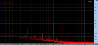

5th, 7th, and 9th harmonic have an excessive level compared to 4th, 6th and 8th.
E810F triode strapped does not suffer from this problem.
But this I discovered a little too late, after buying several dozens D3A...
anybody loving D3A wants to buy some at a bargain price? 😀
E810F triode strapped does not suffer from this problem.
But this I discovered a little too late, after buying several dozens D3A...
anybody loving D3A wants to buy some at a bargain price? 😀
5th, 7th, and 9th harmonic have an excessive level compared to 4th, 6th and 8th.
E810F triode strapped does not suffer from this problem.
But this I discovered a little too late, after buying several dozens D3A…
anybody loving D3A wants to buy some at a bargain price? 😀
You're funny! The 5th is [(93 - 22) = –71 dB] lower than fundamental. This would be inaudible even with sine waves, let alone program music content. The 7th and 9th are even lower.
Do try to recognize the difference between an observation and a result, dear CiroMarzio. The 300B is an outstanding tube to build upon. Magnificent.
GoatGuy
Dirk (LOSI),
In the optics world, lenses have a problem called “aberration”. The worst is chromatic (red and blue refracting different amounts through curved lenses), but there are other forms too. Optical engineers "deal with it" by two main techniques. First is, using more elements, so that the bending done by any given element is less than with fewer elements. Second is, pairing up elements so one partially (or mostly) compensates for the other's chromatic aberration behavior. They're called doublets and triplets.
I bring this up because the same techniques can be applied to high fidelity amplifiers to control and clean up the nonlinear shortcomings of valves in real world operation. The analogy of “use more elements” would be “use more stages”. The analogy of “bend light less” would be “of lower gain per stage”. The analogy for “doublets and triplets” to compensate refraction issues would be “use better biasing and current sourcing techniques”.
So, there you have a basic outline of a design criteria list!
• More, lower gain stages.
• Better biasing.
• Symmetric compensation
One might be tempted to go all faddish-purist, and have a no-capacitor ("direct coupled") amplifier, but this is a bit overblown. Real-world amplifiers with quality components, rightly sized and specified rarely have any audible aberrations based on the DC blocking capacitors influence. But it might be one of your cherished ideals, so if so… include that too.
Anyway, I just wanted to point out the above, in the hopes that if you “get it”, that it will influence the design you choose (or create!).
Have fun! And don't forget to build a really decent power supply for triode mode amplifiers.
GoatGuy
Member
Joined 2009
Paid Member
...after buying several dozens D3A...
anybody loving D3A wants to buy some at a bargain price? 😀
Did you try the 6E5P (triode wired) ? - I heard it driving a 6C4C once, and compared it with a 6C45P driving same output tube. The 6C45P was very clean, perhaps too 'solid state' sounding for some people. The 6E5P was smooth sounding.
this circuit was successfully built by a number of people, most frequently as a pair of mono block amps

You can replace the 417A / 437A with a triode D3a, EC8010, 6C45PI or triode E55L if you wish.
For 1:1 IT you could try the inexpensive Hammond 126B, or similar 1:1 offerings from SP Wound Components, Audio Note UK, Hashimoto, Monolithic Magnetics or Noguchi depending upon the depth of your pockets. I would suggest 1:1 bifilar wound are the way to go.
Nowadays I would definitely use Rod Coleman boards for the 5V filament supplies to the 300B! and be tempted to use SiC diode bias on the input tube
Best of luck
Last edited by a moderator:
SJS: your B- supply circuit is wrong. As shown, it will produce positive voltage, not negative bias voltage. Nice idea though. Pretty complicated transformer.
The chief disadvantage of having [rectifier → choke → capacitor ] power supply stages is that they waste a fair fraction of the transformer's secondary potential. It would be much better to include a 10 μF to 20 μF capacitor before each of the choke stages to act as a "topping up reservoir". Amazing how much more voltage you get.
Let's see. Its also not clear why you're burning up power with that 12 kΩ/20 watt resistor. If it is to drop voltage to 375, I really can't see the point. It certainly isn't to improve the ripple suppression of the choke. Just seems like a room heater, to me.
Same goes for the 15 kΩ, 5 watt resistor burning power on the A+ supply.
The use of a 2,200 μF cap as a cathode-bias-bypass … is about 10× greater than really necessary, but since they're inexpensive parts … why not. Seems OK.
You could have had a 1:2 or 1:4 interstage transformer between the stages, with little (nil) negative effect. Kind of like "free gain". One of the sweet things that transformers are willing to do for free for us. To not take advantage of it is like not using a free airplane ticket.
The rest seems fine. I'm not sure whether I'd be sticking a rheostat on the filament pins of the 300B. Rheostats are notorious for becoming noisy, even when not periodically wiped.
GoatGuy
ADDENDUM: Indeed… if the goal is to produce a magnificently beautiful chassis AND burn watts (which is what your 3-rectifier plus room heater approach affords), you might as well toss in a few 6CA7s, 3 or 4 voltage regulator tube (0A3, etc) and build up a nice series-cathode-follower regulated multi-volt power supply. Seriously! The gas regulators make the prettiest glow, and with some fiddling, you can get a QUITE stable (and QUIET) set of anode supplies going. Heck.. the regulation is so good with the 6CA7 that you might as well go "stereo" instead of mono block (as drawn). They've (6CA7) got plenty of gumbo in the milliamp and plate dissipation departments.
Let's see. 2 of the 6CA7s. Drop the room heater resistors. 2 0D3 (150 volt) regulator tubes plus 1 0A3 (75 volts) gives 375. The 190 can be wrought with a pair of 0B3's (90 volts each). And, to think! each type is a different color! 7 more tubes in the power supply. 2 more tubes for the LEFT channel. 2 more transformers. Paint it all metallic-greeeeeeeen
GoatGuy
Last edited:
SJS: your B- supply circuit is wrong. As shown, it will produce positive voltage, not negative bias voltage. Nice idea though. Pretty complicated transformer.
The chief disadvantage of having [rectifier → choke → capacitor ] power supply stages is that they waste a fair fraction of the transformer's secondary potential. It would be much better to include a 10 μF to 20 μF capacitor before each of the choke stages to act as a "topping up reservoir". Amazing how much more voltage you get.
Let's see. Its also not clear why you're burning up power with that 12 kΩ/20 watt resistor. If it is to drop voltage to 375, I really can't see the point. It certainly isn't to improve the ripple suppression of the choke. Just seems like a room heater, to me.
Same goes for the 15 kΩ, 5 watt resistor burning power on the A+ supply.
The use of a 2,200 μF cap as a cathode-bias-bypass … is about 10× greater than really necessary, but since they're inexpensive parts … why not. Seems OK.
You could have had a 1:2 or 1:4 interstage transformer between the stages, with little (nil) negative effect. Kind of like "free gain". One of the sweet things that transformers are willing to do for free for us. To not take advantage of it is like not using a free airplane ticket.
The rest seems fine. I'm not sure whether I'd be sticking a rheostat on the filament pins of the 300B. Rheostats are notorious for becoming noisy, even when not periodically wiped.
GoatGuy
Nice critique, it's a shame you have never built or listened to such a circuit, as all would become clear.
The B- supply is not wrong, it does give negative rail, I have built 10s of them over the years - go try it
Choke input power supplies go much easier on the mains tx and sound way better, the inclusion of an input cap makes it sound like every other flabby SE amp, so it is not of interest. It is not "much better" with an input cap, it sounds significantly worse. Why bring up "efficiency" a total red hering is SE valve power amp is the purpose, you want efficiency? go build a Class D amp.
The shunt resistors are to provide min current through the choke, always a good idea with a choke input psu imho
I had a pile of 2,200uF 6.3V black gates at the time, hence the design. I have said in my post that I would probably use a diode if doing it today.
The point of a 1:1 bifilar IT is you can get sub 10Hz to >100kHz bandwidth, it is the only sensible option which cannot be achieved with 1:2 or 1:3 or 1:4 options, so it is not "free gain" as you restrict bandwidth and often introduce ringing, if you have ever heard a 1:1 bifilar compared to a 1:2 or 1:4 IT then you would know why
Using the pot on the 300B filament? apart from again stating I would use Rod Coleman supplies if done today, therefore the pot would vanish, I have examples built more than 20 years ago using good 2W wirewound pots which have not gone noisy.
The OP asked for a proven circuit, rather than un-proven conjecture. I have built several versions of this amp, as have more than 10 DIYs I am personally aware of since it was first published 18 years ago.
best of luck
UPDATE
And Series Regulators sound truly awful, please don't suggest that again! 😱
Now, a really good Shunt Regulator, maybe using 300Bs as the pass tube? You could get me interested in that..... see John Camilles 211 Shunt Reg for his 211 SE amp in Sound Practices back in the day 😀
Last edited:
I have opposite experience.
D3a, LED bias, 10mA CCS, 70V RMS out.
Hi euro21.
Have you ever found why this peak at 150Hz?
3rd harmonic of 50Hz or what?
Nice critique...
The B- supply is not wrong, it does give negative rail, I have built 10s of them over the years - go try it
I stand corrected... I see now that the center-tap is heading up the negative rail side of things. I really shouldn't comment at 6 in the morning.
Choke input power supplies go much easier on the mains tx and sound way better, the inclusion of an input cap makes it sound like every other flabby SE amp, so it is not of interest.... go build a Class D amp.
A bit tetchy aren't we, today! Class D indeed. We will disagree on your conjectures though re: 'sound way better' and 'like every other SE'. Power, dude, is power. DC, clean power, with a nice stout reservoir cap close to the finals ... will sound exactly the same whether headed up with a pile of chokes, CLC / LCL / CRC or any other combination of ripple filters.
The shunt resistors are to provide min current through the choke, always a good idea with a choke input psu IMHO
Why? If you recall V(t) = L dI/dt (voltage equals rate-of-current change times inductance) for all inductors, having an additional "minimum" current thru them accomplishes nothing. Sorry ... I think its a bit of rabbit's foot ointment, the minimum-trickle idea.
I had a pile of 2,200uF 6.3V black gates at the time, hence the design. I have said in my post that I would probably use a diode if doing it today.
Hey... I liked the 2200 microfarad cap! But sure... diode works too.
The point of a 1:1 bifilar IT is you can get sub 10Hz to >100kHz bandwidth, it is the only sensible option which cannot be achieved with 1:2 or 1:3 or 1:4 options, so it is not "free gain" as you restrict bandwidth and often introduce ringing, if you have ever heard a 1:1 bifilar compared to a 1:2 or 1:4 IT then you would know why
Tetchy again. Ever wound a trifilar interstage? I have. They also sound great. Or a quadrafilar? Just as pretty. Now if we're just talking about el-cheapo interstages, then you are right: the cheapest bifilar interstage beats out any concentric-winding 1:2 or 1:4 transformer. On this we will agree.
And Series Regulators sound truly awful, please don't suggest that again! 😱
Now, a really good Shunt Regulator, maybe using 300Bs as the pass tube? You could get me interested in that..... see John Camilles 211 Shunt Reg for his 211 SE amp in Sound Practices back in the day 😀
OK, shunt regulators work as well: they're "better" because they leave the final DC reservoir "naked" as far as the final tubes are concerned - naked as in being able to supply whatever instantaneous current desired to reproduce the program material. Shunt regulators that do not have a post-regulation reservoir capacitor ... would very probably sound like crap, because of their internal plate resistance and its attendant voltage drop. Or, if you prefer, their current sourcing limits. But, hang some nice big reservoirs on the cathode (output) side, and you get back all that instantaneous current sourcing. Plus ripple suppression that can be an order of magnitude better than big inductors.
The real problem here isn't my critique (short of the mistake with the negative B- power supply), but rather that you've got a LOT of pride-of-ownership in this design, and are defending it vociferously. I really don't doubt that it is a sweet amplifier in the end. I was merely going point by point and giving some of my observations. And, since I've built dozens of amplifiers of varying designs, I can appreciate the pride of ownership side of things too. I can.
lastly, I offer an apology: for adding that addendum regarding more tubes, flashy lights and steampunk sentimentalities. It was gratuitous, and for that I'm sorry. (But understand too: I like the way gas regulators glow!)
Yours, GoatGuy
Hi euro21.
Have you ever found why this peak at 150Hz?
3rd harmonic of 50Hz or what?
It's due to the (D3a, powerdrive, 300B SE) first stage's HT ripple.
The HT PSU is simple: 5U4G, after the common c-r-C-L-C (4u7-100R-47u-10H-47u) separated R-C (3k9-47u) for each stages.
Dear all,
thanks for the input. Haven't got everything, I like to ask some more questions:
GoatGuy:
As you reommended me the following
So, there you have a basic outline of a design criteria list!
• More, lower gain stages.
• Better biasing.
• Symmetric compensation
You approach would be rather a 3 stage approach?
Symmetric compensation; do you have some more explanation or examples?
Which circuit would you use for a 3stage apporach?
SJS:
I have seen your circuit already.
I can easily adapt the D3a to the circuit?
You mentioned you`d use a diode for biasing the input tube nowadays. That means you would left the resistor and the cap?
Would you use a different OPT than 1627 SEA (I know tha this is not easy to answer, but which OPT are you preferring and why?)
In your circuit, you use fixed bias. Could I go for the auto bias?
I will waste 70V, might be difficult to gain.
Sorry for my several questions, but I like to find the right approach from the beginning.
regards
Dirk
Ii my experience D3A is an excellent driver tube on paper but have some irregular harmonic distortion decay.
If you do not have problems in sourcing them, E810F could be a better choice.
THD spectrum is usually much more regular and the sound more natural.
Also they have an even lower internal impedance that will make easier to find a good IT for them.
Agree with E810F if you can, but D3A is still pretty darn good.
My advice would be to start from the specs sheets and work backwards from the finals to the input. It is not so difficult...
Then you will start the hard work. Power supply, heater supply, layout, etc.
Ian
6E5P I have not tried yet. The high input capacitance worried me. But I am very interested in your experiences. Have you used it in triode mode? It looks like a near equivalent of E55L (also not easy to drive)Did you try the 6E5P (triode wired) ? - I heard it driving a 6C4C once, and compared it with a 6C45P driving same output tube. The 6C45P was very clean, perhaps too 'solid state' sounding for some people. The 6E5P was smooth sounding.
6C45P is another tube that looks good on paper but I do not like. I do not understand what is wrong with this tube, but I have the sensation it lacks a considerable part of the harmonics.
D3A gives the sensation of having all the harmonics, but not in the right proportions.
On the other hand, I love the sound of triode strapped E180F / 5A160K.
That could be an interesting driver if one is not willing to push 300B to the limit (keeping it within 7-8 W).
Or could make an excellent input tube in a 3 stages amp. I would go for E180F-45-300B
have fun!
Ciro Marzio - Luthier and Free Lance Audio Designer
Dear all,
looking for a new project with 300B, I thought to build an amp with an IT.
As a driver, I like to use a D3a (strapped to triode).
(I don't want to use the usual 5842 tube. I like to use the IT in 1:1 configuration)
Does anybody have a proven circuit which I can take as basis?
I built once the 6SN7-300B amp. However, I'm not so experienced to create on my own experience this circuit.
I want to use my existing Hammond OPT 1627 SEA.
I'm open to source a more advanced when it is feasible.
(I mentioned in a different thread, I was not impressed about the sound quality of the 6SN7-300B with 1627 SEA; Walton design).
I have as a comparison an Unison Research Sinfonia (KT88 PSE).
Any help from your side is appreciated?
thanks and regards
Dirk
Take a look at my 300B SE with interstage. It works with a D3a as driver, but I changed to ECC88 with parallel triode units (sounds better to my ears). My unit has parallel 300B for more power, but the circuit will work fine with a single 300B if the OPT impedance is right (which will be the case for you, as you already have a suitable OPT).
Dear all,
thanks for the input. Haven't got everything, I like to ask some more questions:
GoatGuy:
As you reommended me the following
So, there you have a basic outline of a design criteria list!
• More, lower gain stages.
• Better biasing.
• Symmetric compensation
You approach would be rather a 3 stage approach?
Symmetric compensation; do you have some more explanation or examples?
Which circuit would you use for a 3stage apporach?
SJS:
I have seen your circuit already.
I can easily adapt the D3a to the circuit?
You mentioned you`d use a diode for biasing the input tube nowadays. That means you would left the resistor and the cap?
Would you use a different OPT than 1627 SEA (I know tha this is not easy to answer, but which OPT are you preferring and why?)
In your circuit, you use fixed bias. Could I go for the auto bias?
I will waste 70V, might be difficult to gain.
Sorry for my several questions, but I like to find the right approach from the beginning.
regards
Dirk
Dirk, I would not worry too much about the OPTs: use the 1627SEA you already have. You can change them later.
But focus on a truly great quality power supply irons and truly great quality IT.
On bias: IMHO well made fixed bias sounds way better than auto bias.
But once again the quality of the bias supply is paramount. Consider SJS bias supply (which is better than 99% of what you see around) as the bare minimum to get good results.
I agree with Goatguy that a 3 stage amp can do better, if very well designed and built.
I also agree with Goatguy that capacitor input filters in the power supply do sound better.
But they have a big problem: if your power transformer sucks you are going to know it.
Unfortunately the vast majority of power transformers on the market are poor quality items. This means that also SJS is often right... audio can be a complicated thing
Ciro Marzio - Luthier and Free Lance Audio Designer
Take a look at my 300B SE with interstage. It works with a D3a as driver, but I changed to ECC88 with parallel triode units (sounds better to my ears). My unit has parallel 300B for more power, but the circuit will work fine with a single 300B if the OPT impedance is right (which will be the case for you, as you already have a suitable OPT).
Very Nice blog! you are in Zürich? I am in Thalwil. It might be interresting to meet and share ideas some time. 🙂
- Home
- Amplifiers
- Tubes / Valves
- 300B SE with an interstage