I think marce was responding to an earlier question I posed about what capacitors are required when Tentlab shunts are used. I asked whether some of the local decoupling capacitors are still needed... Didn't mean to cause a problem, just trying to understand what others have tried etc.
Even with different external supplies such as the Tentlab shunt, you want to leave the 100nF caps (hopefully placed right next to the power pins of the active device (s)) where they are and not remove them. I was worried when I saw these listed as possible caps to remove from the board when adding the above shunt regulators, this would only be detrimental to the design, by adding noise to the overall power delivery system... So I am saying that these caps should be left alone.
If you're mounting your new regulators and their associated 100n film caps into the original mounting holes for the 100n caps which were on the board, then you're talking about millimetres of difference. I can't see how it can be done any different/better.Even with different external supplies such as the Tentlab shunt, you want to leave the 100nF caps (hopefully placed right next to the power pins of the active device (s)) where they are and not remove them. I was worried when I saw these listed as possible caps to remove from the board when adding the above shunt regulators, this would only be detrimental to the design, by adding noise to the overall power delivery system... So I am saying that these caps should be left alone.
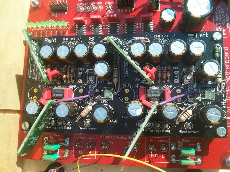
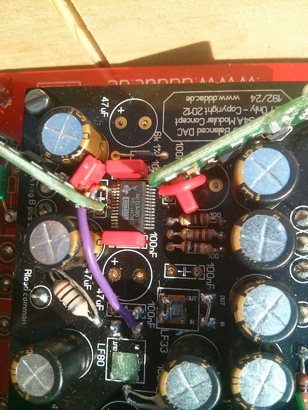
Ignore the rest of the electrolytics in these pictures as I've changed those since, but this is how my shunt regs and 100n caps are arranged.
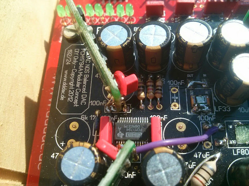
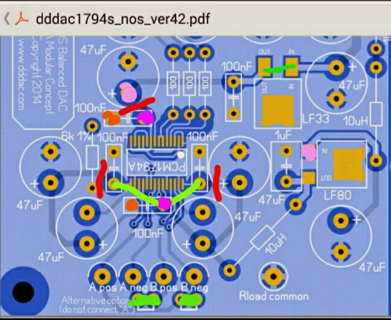
Here's a crappy diagram explaining what I did there. I also cut a couple of traces (in red) and added a couple of short wires under the boards (in green) to reduce the trace distance from the analog 8v regs to the dac chips.
PTH decouplers are doing nothing anyway totally useless they should be SMD parts next to the pins, design is compromised to start with, a SMD small case cap across the pins would be an improvement especially with the added shunt supplies....
maybe so, but this is a 28 pin SSOP component with 0.65mm spacing between the legs, so unless you're some kind of soldering wizard, that's going to be well outside of the scope of what most people can achieve. Bear in mind this is a user friendly kit DAC that people with a huge variety of experience and ability can all enjoy building and tweaking.a SMD small case cap across the pins would be an improvement especially with the added shunt supplies....
I am aware, but tweaking the decoupling on a 24 bit DAC is not a good idea, the layout really could do with some SMD 0805 (preferably smaller) locations next to the supply pins...
...please allow me a question: what is it then ? I can't believe that it might be your DDDAC ?
Hi Rheinhard,
I am in the process of building new speakers, my current speakers are playing on a very high level, they are very refined, transparant and balanced and able to portray all changes being made downstream. But field coil sprakers have stolen my heart for their infinite dynamics and openness 😉
The source however has always been the bottle neck, how good the dac is, there is always a way to improve.
The next step is still synchronous streamer with a bbb and tp cape

But who knows? It might be the last step? Than I shall look out for another hobby 😀
From looking at the various uploaded photos, some folks appear to have removed 100nF capacitor to make way for attaching the shunts right next to the DAC chip.
So, for example, to place the 8v shunt closest to the DAC chip, some folks have removed C23/C26 and reused this position to locate the shunt millimetres away; and to place the 3.3v shunt closest, other folks have removed C28/C30 and reused this position.
Or maybe I am missing something and these folks have mounted these capacitors underneath the board.
The shunts are faster than a cap and over a wider frequency range. Also: on the output of the Tent shunt there is a small cap present. Thats why you can lose the cap at the dac pin if you solder the shunt at that same spot as James illustrated.
Too much capacitance between the shunt and the consumer will only slow down the supply current.
I agree with putting small smd caps right at the pins of the dac, but that is not possible in this pcb layout. Hopefully a provision will be made in a new revision of the board. A long with an on board shunt right at the power supply pins.
Last edited:
The shunts are not faster than a cap next to the pins, plus the added inductance negates that speed, sorry but position is everything and any stray inductance is the killer....
The order of supply is...
On chip capacitance...
Board planes capacitance (if planes are used)...
Local decoupling capacitors next to the pins (low value smallest package possible, 0402)...
Reservoir capacitors...
Power Supply...
This is how the instantaneous power requirements are met for any switching digital circuitry. So 0402s pre-fitted next to the pins would be a benefit.
Hi guys,
I've just been reading over Miero's BBB Botic driver instructions as I'll be moving to using synchronous reclocking of the i2s data to my dddac, and I spotted a software option to get the BBB to output as either i2s (default) , left justified or right justified.
From the Botic driver page
Now I note that the main function of the 'front end' of the mainboard is to convert i2s to a right justified signal.
From Doede's documentation:
So, it looks like it's possible to set the software to natively output RJ and I guess connect this direct to the data lines at the DAC decks rather than the regular i2s port on the mainboard?
Anyone tried that or got a good reason why I shouldn't?
It looks like a nice way to remove some complication from the audio chain unless I'm missing something?
Cheers,
James
I've just been reading over Miero's BBB Botic driver instructions as I'll be moving to using synchronous reclocking of the i2s data to my dddac, and I spotted a software option to get the BBB to output as either i2s (default) , left justified or right justified.
From the Botic driver page
------------ McASP format ------------
Clock source and polarity for I2S mode is configurable via: - kernel option snd_soc_botic.mcasp_format - file /sys/module/snd_soc_botic/parameters/mcasp_format
Supported values:
+1 ... I2S mode
+2 ... Right Justified mode (LSB)
+3 ... Left Justified mode (MSB)
Now I note that the main function of the 'front end' of the mainboard is to convert i2s to a right justified signal.
From Doede's documentation:
On the Mainboard the I2S Data from the WaveIO board (or external...) is led directly to the I2S - right-justified (RJ) converter. Which is built up from 5 times the 74VHC164 shift registers to get the 7 clock cycles delay for the right channel and (32+7) 39 clock cycles for the left channel.
So, it looks like it's possible to set the software to natively output RJ and I guess connect this direct to the data lines at the DAC decks rather than the regular i2s port on the mainboard?
Anyone tried that or got a good reason why I shouldn't?
It looks like a nice way to remove some complication from the audio chain unless I'm missing something?
Cheers,
James
Last edited:
I believe the other part of the main board function is to split the left and right signal and arrange for them to arrive at the appropriate dac chip to allow play of the left and right data at the same time.
That's my understanding as I was looking at using ian fifo to do the same.
Perhaps if miero could separate the data into separate left and right channels for dual mono dacs, but that sounds very freaking hard and probably not used by many.
I and I2S to pcm board does have dual mono outputs but whether these are synced left and right to arrive at the same time.
Hope that helps(Correct).
Laters,
Drew.
Ahh yes, I knew I was missing something.
I note that the driver has 4 outputs and if it can change from left justified to right justified then it seems it has all the base ingredients there,but as you say, it's a fairly specific output mode that wouldn't be used by many
I note that the driver has 4 outputs and if it can change from left justified to right justified then it seems it has all the base ingredients there,but as you say, it's a fairly specific output mode that wouldn't be used by many
Doede,
when you have some time, could you explain a little about the data signal generated by the mainboard that goes to each channel on the dac decks please? I've had a read of your site but wasn't sure how the dac chip in mono mode accepts the signal.
Are you sending both the left and right data to each channel and it only uses half of it?
I'm asking because Miero has confirmed that the BBB Botic driver can generate multiple data signals and it can separate the channels if necessary, so I would like to try feeding 2 data signals direct to the dac decks and see how that compares with using the shift register. But for this, I need to understand what type of signal we are aiming for.
thanks,
James
Doede,
when you have some time, could you explain a little about the data signal generated by the mainboard that goes to each channel on the dac decks please? I've had a read of your site but wasn't sure how the dac chip in mono mode accepts the signal.
Are you sending both the left and right data to each channel and it only uses half of it?
I'm asking because Miero has confirmed that the BBB Botic driver can generate multiple data signals and it can separate the channels if necessary, so I would like to try feeding 2 data signals direct to the dac decks and see how that compares with using the shift register. But for this, I need to understand what type of signal we are aiming for.
thanks,
James
Hmmm, maybe I can answer that as I played around with measurements of the I2S bus. Basically, the description and alignment is shown in the PCM 1794 datasheet in detail.
In mono mode, the right and left channel is the very same, so, the data pattern is the same when the word clock is high and low.
However, I doubt that bypassing the shift registers will make a significant difference, the data will stay the very same (it must be bit correct in both scenarious), so the only difference could be jitter from the shift registers, which is - to my mind - neglectable.
Best Regards,
Hermann
Hi James,
not sure what to explain... Basically inside the 64 clock cycles of one Stereo sample, you have two times 24 bits normally the dac makes sure Left and right Signal are again rime synchronous. With two mono Chips this is of course NOT the case, hence my glue logic to delay one channel an extra 32 bits.
So Splitting left and right data is one part, delaying 32 bits is the final step.
Hope this clarifies a bit?
Thanks guys. If I can output 2 data signals; 1 left justified and 1 right justified, would this be suitable?
Hermann, yes, I guess the shift registers are so simple that it's unlikely they add any issue, but it seems to me that it might be very easy to try, so maybe it's interesting to have a go 🙂
If it works, it's even possible to reclock 2 data signals with the s03 as the DDDAC doesn't use the mck channel.
But I have a few things to finish before I get any time to have a play with this. I am almost done with my build into 2 x hifi2000 cases with 1 for a multirail power supply and the other for BBB, s03 reclocker and dddac. I'll post some pictures up very soon...
Also, just about to add new clocks to the s03 so it will do synchronous clocking from the BBB as this seems to be the best solution for i2s source at the moment
Got my u.FL connectors sorted today and I swear it's better just from swapping to those instead of cheapy jumper leads for the i2s.
Dddac to u.FL and bbb to u.FL are from Ackolabs
Sounding very sweet tonight with great detail in the high frequencies 🙂
Dddac to u.FL and bbb to u.FL are from Ackolabs
An externally hosted image should be here but it was not working when we last tested it.
An externally hosted image should be here but it was not working when we last tested it.
Sounding very sweet tonight with great detail in the high frequencies 🙂
They're from Ackolabs, although not listed on his website. Might be worth a group buy.Looks good, James!
Where does that nice litlle Ufl adapterboard come from?
Ed
- Home
- Source & Line
- Digital Line Level
- A NOS 192/24 DAC with the PCM1794 (and WaveIO USB input)