
Mr. Pass,
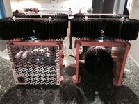
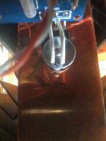
I wish I knew what was/is wrong... I built these in 2011 and have had them sitting around since. I installed the Q1-2 transistors incorrectly and it failed the light bulb startup and scorched r2.
I've looked at them every time I've parked in the garage for the last 4 years. I decided today that I was either going to pitch them in the garbage or I was going to try to get them working. I ordered and received new transistors in 2011; I installed them today. This was no easy feat because of the design of the amplifiers; the reason why I have been avoiding it. After the installation I put it on the bulb tester and the bulb (100w) glowed briefly and then went out. I removed the bulb tester and tried to bias one amp. I'm pretty sure I zeroed the pots but I'm not getting any readings on the outputs for dc offset or the output resistors as I turn the pots. I really don't have a deep knowledge about circuits, just enough to make me dangerous. I breezed through the process of making the B1 preamp, so I was hoping the F5 would be a similar experience; not so. At this point, I don't know if I damaged other components or how to trouble shoot the existing ones on the boards. It may be best, at this point, to try and salvage the heat sinks, bus bars and torodials for another design.
Best regards,
Eddie
Attachments
erpiiii,
please read carefully the whole F5 manual:
http://www.firstwatt.com/pdf/prod_f5_man.pdf
to understand how this very simple circuit works. After that the measurements will begin to make sence. Check you power supply, the values and orientations of all parts. Also, check if semiconductors are faulty or not (burned resistor usually means that something else in the circuit died too, usually a semiconductor).
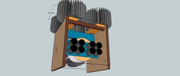
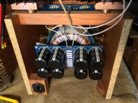
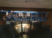
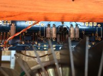
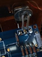
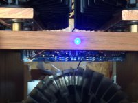
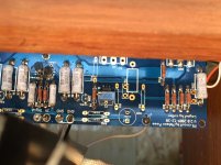
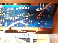
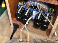
High resolution pictures of PCBs and wiring will help.
please read carefully the whole F5 manual:
http://www.firstwatt.com/pdf/prod_f5_man.pdf
to understand how this very simple circuit works. After that the measurements will begin to make sence. Check you power supply, the values and orientations of all parts. Also, check if semiconductors are faulty or not (burned resistor usually means that something else in the circuit died too, usually a semiconductor).
High resolution pictures of PCBs and wiring will help.
I decided today that I was either going to pitch them in the garbage or I was going to try to get them working.
Neat design, Eddie! Don't give up on them!
I have checked the voltage from the power supplies they measure 25.4 +/- volts on each amp. I can plug them in and the led lights with no smoke. Here are some more pictures as requested.
Attachments
Not really... I've 2 days where I'm condemned to sit in Park City with nothing to do but ski and eat... so meeting somebody new and helping with an audio project just makes it sound like more of a perfect trip!
Oh.
Well then, nevermind...

are you sure you're pots are in correctly?
I'm not familiar with cviller's boards but I thought they are oriented opposite to each other. I could be wrong though....
Yes, that may be the case.
You are a most generous guy, Jim.
Yes, he is, as are you!
He dropped by and walked me through the biasing process. Between me looking at the wrong meter when checking the PS voltage and not wanting to blow something up, I had an aversion to turning the pots enough to see the voltage rise. I also discovered that my heat sink design is overkill! So far they are barely warm!
Thanks again, Jim, for making the time to drop by while in SLC, it was greatly appreciated!

- Status
- This old topic is closed. If you want to reopen this topic, contact a moderator using the "Report Post" button.
- Home
- Amplifiers
- Pass Labs
- Looking for help with Pass F5 mono's in Salt Lake City area