I would add, if input diff pair is well matched and has low drift, considering moderate Av=21, maybe you can replace C with short. Let's say, if BJT's are matched to 0.5mV Vbediff, overall DC offset would be 10.5mV, possibly tolerable for power amp.
Ha ha, It really cross my mind. I am using 300ohm degenerate resistor on all 4 BJT of the complementary LTP, if I use a matched dual transistor, I might get away with DC closed loop. I have cascode on the diff pairs, I can use 35V to 40V transistors. I really don't like large size caps, make the pcb bigger....$$$, caps......$$$$, might as well consider match pairs.
Yeh, I am not familiar with the name bipolar and polar when I read the posts.
Last edited:
Just be aware of the additional offset that could arise from base currents flowing through DC resistance seen from inverting and non-inverting inputs. If symmetric pnp/npn diff pairs are used, base currents subtract resulting in lower added offset.
Keep in mind, KISS is mighty powerful approach, after all perhaps electrolytics are not so bad.
Keep in mind, KISS is mighty powerful approach, after all perhaps electrolytics are not so bad.
Last edited:
What is KISS?Keep in mind, KISS is mighty powerful approach, after all perhaps electrolytics are not so bad.
I want to confirm, polar electrolytics are normal electrolytics with +ve and -ve terminals. That the +ve terminal cannot be more negative than the -ve terminal.however
a pair of back to back bi-polar electrolytics have very low distortion and are nearly upto plastic film distortion performance.
Similarly back to back polar electrolytics are much lower distortion than single polarised and may exceed the distortion performance of a single non-polar electrolytic.
Bi-polar electrolytics are non-polar that you can turn the cap around, the cap can take +ve and -ve voltage.
I am not familiar with these name and I don't want to guess.
This is a bipolar 220uF from digikey, is this good?http://www.digikey.com/scripts/DkSe...uq=635578863270367100&CSRT=748577047426600569
Thanks
Last edited:
I am not familiar with these name and I don't want to guess.
Let me google that for you
Is that so hard?
This is what I come up. I use a 220uF bi-polar electrolytic http://www.digikey.com/scripts/DkSe...uq=635578984958817802&CSRT=748577047426600569 in parallel with a 1uF polypropylene http://www.digikey.com/scripts/DkSe...uq=635578968036000498&CSRT=748577047426600569.
I think I choose the right thing for low distortion. Please comment if this is not good.
Thanks
I think I choose the right thing for low distortion. Please comment if this is not good.
Thanks
Check out this thread starting at post 19 for two alternatives to reduce DC offset - I always use method #2, which favors jfet or mosfet input stages. A servo can count as method #3, but I have never needed one with sufficient matching for the input diff pair. Method #2 would very well with the Madisound bargain bin polypropylene caps mentioned earlier in this thread.
http://www.diyaudio.com/forums/chip-amps/28276-feedback-capacitor-minimize-dc-offset-2.html
http://www.diyaudio.com/forums/chip-amps/28276-feedback-capacitor-minimize-dc-offset-2.html
paralleling with a small film does squat as far as is objectively known - with >100:1 ratio it simply can't make more than 1% difference on the presumed "errors" of the bigger cap at audio frequencies by simple math
Bateman didn't find distortion in Al electros to be proportional to esr so even the breakpoint of the 1 uF with the Al electro's esr isn't expected to matter - and its way above "conventional audio" frequencies - you know those that it can be easily shown most humans hear with their ears
Bateman didn't find distortion in Al electros to be proportional to esr so even the breakpoint of the 1 uF with the Al electro's esr isn't expected to matter - and its way above "conventional audio" frequencies - you know those that it can be easily shown most humans hear with their ears
Last edited:
using servos comes with added complexity and unforeseen problems,
integrators tend to magnify capacitor short comings closed around a 120 dB loop.
Ive seen common problems in PLL filters eg integrator using X7R capacitors , micro-phonics causing high bit errors,
integrators tend to magnify capacitor short comings closed around a 120 dB loop.
Ive seen common problems in PLL filters eg integrator using X7R capacitors , micro-phonics causing high bit errors,
Last edited:
paralleling with a small film does squat as far as is objectively known - with >100:1 ratio it simply can't make more than 1% difference on the presumed "errors" of the bigger cap at audio frequencies by simple math
Bateman didn't find distortion in Al electros to be proportional to esr so even the breakpoint of the 1 uF with the Al electro's esr isn't expected to matter - and its way above "conventional audio" frequencies - you know those that it can be easily shown most humans hear with their ears
This is not for distortion. It is established that distortion is not important as the 220uF cap is very low impedance even at 20Hz. Parallel a 1uF to keep the loop closed at higher frequency where the loss of the 220uF increase with frequency.
Check out this thread starting at post 19 for two alternatives to reduce DC offset Method #2 would very well with the Madisound bargain bin polypropylene caps mentioned earlier in this thread.
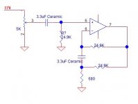
Very interesting. I drew out the circuit with values. I choose the small cheap ceramic 3.3uF cap. Distortion is not even an issue because the break frequency is 1/(6.28 X 25000 X 3.3 X 10-6 = 2Hz. At 20Hz, the reactance is 2.5K which is a lot lower already. I can even find 10uF in 0.2 lead spacing. That will kick the frequency below 1Hz.
I want to use ceramic for the smaller size. The summing junction is the most critical point of the opamp and a big film cap can pick up noise.
Attachments
Last edited:
This is not for distortion. It is established that distortion is not important as the 220uF cap is very low impedance even at 20Hz. Parallel a 1uF to keep the loop closed at higher frequency where the loss of the 220uF increase with frequency.
id rather suffer a small rise in cap impedance than resonance interactions jcx is talking about.
what's the rise in impedance at HF do to the gain >> not much
most caps that size are spec'd at 100KHz these days I'b more concerned with leakage current
Last edited:
I search JCX's response in this thread, I did not see any mention or resonance.id rather suffer a small rise in cap impedance than resonance interactions jcx is talking about.
what's the rise in impedance at HF do to the gain >> not much
most caps that size are spec'd at 100KHz these days I'b more concerned with leakage current
The idea is for the smaller cap to continue to lower the impedance when the inductance of the large cap kicks in. That's pretty standard practice. Even my Acurus uses 0.47u//220uF.
The cap I chose spec max 3uA at rated voltage across, which is 50V. This cap never going to see more than 2Vpp swing.
Last edited:
Do you have any article or thread talking about resonance when parallel two caps?high current bypassing and this cap at signal level is rather two separate things
But the idea is the same, you want to keep the impedance low at high frequency to keep the closed loop gain constant, not going down. Amp can go into instability when closed loop gain reduce and high frequency.
it has been pointed out that the inductance is seldom much more than that of the distance between the leads in modern electrolytics
big electrolytic cap Z certainly won't rise to feedback ratio upsetting few hundered Ohms by the at most low single digit MHz loop gain intercept of most audio power amps
the self resonance frequency of uF film caps can be about there depending on construction - but I didn't initially mention that
big electrolytic cap Z certainly won't rise to feedback ratio upsetting few hundered Ohms by the at most low single digit MHz loop gain intercept of most audio power amps
the self resonance frequency of uF film caps can be about there depending on construction - but I didn't initially mention that
I just did a quick search, one thread comes to my attention. http://www.diyaudio.com/forums/power-supplies/88911-paralleling-capacitors-avoiding-resonance.html
I use VNA a lot before, people really need to be careful in doing measurement, they need to be terminated well with short leads. When comes to over 10 MHz, the testing technique is completely different. Circuits have to be breadboard onto copper plane, using coax with ground solder onto the ground with less than 1" lead, the signal wire has to be very short. If you use a probe and no termination, you see all sort of resonance peak just from the reflection of the long probe lead.
I am not saying there is no resonance, I sure like to read some article talking about this. The test set up comes into question if you are dealing with higher frequency. You can make perfect square wave of few MHz looks like ringing city if the set up is wrong, long ground leads, signal wire and lack of termination will give false result.
Last edited:
220uF with a 500r will not be low distortion at 20Hz.This is not for distortion. It is established that distortion is not important as the 220uF cap is very low impedance even at 20Hz. Parallel a 1uF to keep the loop closed at higher frequency where the loss of the 220uF increase with frequency.
The cap is seeing some AC signal voltage and will distort.
- Status
- Not open for further replies.
- Home
- Design & Build
- Parts
- 220uF cap for GNFB