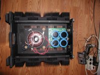
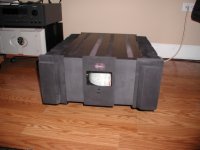
Somehow got unsubscribed to my post...attached is a pic of teh amp inside after sandblasting and anodizing. The amp chassis is a KSA-300 that was parted out - I got the amp chassis and the Power Supply. I sold off the power supply...you can see the six heat sinks - I now have a 1/2" thick 4" wide by 18" long aluminum plate bolted to the sinks via single bolt - I will see if I can take more recent pics...
Attachments
yes, you are wrong.I believe that the voids filled with thermal grease or pad is a LOT LESS conductive than the metal to metal. If I use paste, I will have entire face area conducting through the paste, limiting heat transfer, while using metal to metal (no thermal grease) will have tiny voids, but a majority of the face is in direct contact....yielding the best heat transfer...
Surfaces appear machined...
Am I wrong here??
The most important part of the interface for heat transfer is to avoid air pockets.
Every solid or liquid material that can be used instead of air will be more conductive. Is there any non gaseous material that has more Thermal resistance than air? Materials that use or contain air pockets don't count.
The bar is bolted to the sink.
It will make many metal to metal contacts. These contact POINTS are the tops of the mountainous surface irregularities. The AREA of actual metal to metal contact is a tiny proportion of the whole bar area.
The way to reduce the thermal resistance is to REPLACE the AIR with a better material. Thermal paste is DESIGNED to have low Thermal Resistance. (BTW, grinding and polishing is just another way to replace the air pockets with a better material.)
It is used to ONLY fill in the AIR POCKETS between the contact POINTS.
It is NOT used to create a continuous "layer".
The best bar to sink thermal contact is to use just enough thermal paste and clamp the bar so tightly and so often that all excess paste is squeezed out from the interface. No other material can do better than that.
Why, because ANY extra layer is not as good as metal to metal.
Some are now talking about carbon types as good conductors. But these insert a LAYER between the metal to metal and you are still left with all the holes filled with air.
One could add thermal paste to fill the air pockets left on both sides of the carbon film. That will still have an EXTRA LAYER in the interface.
Now let's see them developing a New Improved Thermal Paste using the carbon technology as the conductive material in the paste.
That has a big potential if the material is so much better than the silver used in the "best" materials.
I suppose they could use diamond but the diamond is expensive and it must be quite difficult/expensive to grind the diamond particles small enough to compare to the particle sizes in more convential Thermal Pastes.
maybe carbon based Thermal Pastes will become available at affordable prices.
How easy to fake a BLACK paste with any other BLACK material??????
Last edited:
Diamond based TIM are available, and not terribly expensive:
Antec FORMULA 7 Thermal Compound - Newegg.com
Uses Zirconium...
There's also liquid metal (conductive/toxic!!):
Coollaboratory Liquid Ultra 100% Metal Thermal Interface Material - FrozenCPU.com
Antec FORMULA 7 Thermal Compound - Newegg.com
Uses Zirconium...
There's also liquid metal (conductive/toxic!!):
Coollaboratory Liquid Ultra 100% Metal Thermal Interface Material - FrozenCPU.com
In the PC overclocking scene, there have been tons of tests with mirror polished surfaces together, and those same surfaces together - with thermal compound in between. The difference has always been massive, with the thermal compound application in favor.
Never skip the thermal compound. There is no time when it is better to not use it. Unless you WANT the extra heat.
Never skip the thermal compound. There is no time when it is better to not use it. Unless you WANT the extra heat.
OK, I am going to perform a little test - just to sate my curiosity.
A properly working CPU chip (AMD 1.2ghz - surface cleaned off with Acetone) with a 1" x 1" flat / polished copper shim between the chip surface and the anodized aluminum heatsink, and one with thermal paste between chip surface and copper shim and between copper shim and same heatsink. Same clamping force sandwiching the whole setup.
Measure temp of heatsink with fan. The higher temperature heatsink would yield best overall heat transfer through questioned interface (since thermal differential drives heat transfer). Since the argument is any thermal paste would be better than bare metal contact, so I will use what I have - basic thermal paste from Rat Shack. Temps taken after 3 minutes and 10 minutes.
I know it may seem to be a waste of time to some of you, but hey, I always wondered....
The only way to ensure some consistency is to use no thermal paste at all as the efficiency of transfer is quite dependent on the thickness of the application layer. At 30W dissipation a 0.1 C/W difference between applications will translate to 3 degrees temperature difference.
And then the shim will definitely lose as there is no way you can get the junction 'flat' enough.
It's very tough to get thermal paste below 0.15C/W, the best pastes with the best applications can get there but it needs repeated trials.
Also note that CPUs and single die semis transfer heat very differently. The ratio of surface area between the the emitter and sink plays a role in heat transfer too.
However, it's your experiment, so don't let anyone stop you!
OK, as silly as it seemed...I ran the test with paste and without.
After 10 minutes with paste, 110F (all temps taken from BIOS - CPU Core Temps)
After 3 minutes with bare copper shim and no paste anywhere (removed with Acetone) 110F ...I shut down the computer as I have been convinced / it was not going as well as I would have thought...
I am a dope. I know. Just had to prove it to myself...
Last edited:
It's good that you tested it yourself; you should never take what anyone else says for granted....I am a dope. I know. Just had to prove it to myself...
There is a sensible limit to the "Thomas Theorem".
One sometimes accepts what one is told after analysing what is wheat and what is chaff.
One does not dissect a 3pin regulator to prove that all three pins are actually connected to the circuit buried inside. One accepts the word of others and builds in the 3pin regulator.
Just as papers describing Thermal Transfer operation will tell one that bare metal to metal interface is not good.
I disagree. First of all, it's good to test everything because knowledge gained by reading just doesn't sink in the same way that first hand experience does. Secondly, even the most basic of facts frequently turn out to be wrong or misinterpreted. For example, in the world of bicycles it was long assumed that skinny, high pressure tyres were faster, and indeed there were plenty of measurements demonstrating that, and a sound theoretical explanation for it. But it's actually wrong once you test the complete bicycle+rider system. More recently, news that microbiologists have been making a basic mistake in culturing bacteria for a hundred years.There is a sensible limit to the "Thomas Theorem".
One sometimes accepts what one is told after analysing what is wheat and what is chaff.
One does not dissect a 3pin regulator to prove that all three pins are actually connected to the circuit buried inside. One accepts the word of others and builds in the 3pin regulator.
Just as papers describing Thermal Transfer operation will tell one that bare metal to metal interface is not good.
Wider tyres have lower rolling resistance, but higher aerodynamic drag. This makes them faster overall under at least some conditions. At some point the increased drag must outweigh the reduced rolling resistance, but apparently no one has actually tested that yet, despite bicycles being almost 200 years old now.faster or less drag?
The thermal paste is only there to fill in the microscopic indentations of the two mating surfaces, any more and you are providing an insulating layer.
That depends on its plasticity which is naturally limited by its respective "atoms" i.e. the largest of its constituents. Actually this thermal paste is supposed to perform an impossible job, it should be not-conductive - isolator - for "electricity" but should be heat-conductive. Consequently , their thermal resistance is about 500- fold higher than the thermal resistance of copper, which is also known as low resistance electrically conductive.
Physics of conductivity is somewhat hard to beat.
Sure enough yes. However, at least i have not seen some calculation of size of heatsinks here. Neither for the other way round, one has a heatsink with particular dimensions, how does one calculate the maximum output power of an amp to be build around this heatsink? How does one calculate the thermal resistance of a heatsink having particular dimensions? It is all simple, but i think this should be done for every diy amp.and you could have mentioned that the thermal paste has a better thermal conductivity than the air it is intended to replace.
That is it's main Thermal Purpose: to exclude air (and other gases) from the heat transfer interface.
Last edited:
There are many posts describing the calculation method.
There are many app notes describing the calculation method.
There are a few free software packages that estimate the Rth s-a of custom heatsinks. But most manufacturers give all the data to determine the de-rated Rth s-a when DeltaT is not 70C to 80C degrees.
The bigger problem, is determining the typical heat load that needs to be dissipated for an amplifier reproducing music at typical average output levels of -30dB to -10dB ref maximum output power.
.................Consequently , their thermal resistance is about 500- fold higher than the thermal resistance of copper...............
and you could have mentioned that the thermal paste has a better thermal conductivity than the air it is intended to replace.
That is it's main Thermal Purpose: to exclude air (and other gases) from the heat transfer interface.
and now you find that your 500fold conductivity ratio is completely irrelevant.Sure enough yes..................
It's the excluded air the matters far more than anything else.
Include air in the interface and you are guaranteed poor thermal performance.
- Status
- This old topic is closed. If you want to reopen this topic, contact a moderator using the "Report Post" button.
- Home
- Amplifiers
- Solid State
- Attaching Aluminum bar to heatsink - thermal paste or pads?