Redesigning (or full designing) a full, working, high power amplifier may be a little too much for a few posts in a thread 😉
I think our friend crazymechanic would be better served by straight suggesting him a fully developed , working , well proven circuit. 🙂
Just sayin' 🙂
Oh , come on ... are you joking. 😀
That is the "badger" amp - DIYA's amp - they sold hundreds, no complaints.
(flipped around , of course)
It even has a review. 🙄
Edit - with a 100pF capacitor at VAS , you could most likely pee on that input stage -
and it would work.
OS
Last edited:
Your joke is much better than mine 😉Oh , come on ... are you joking. 😀
That is the "badger" amp - DIYA's amp - they sold hundreds, no complaints.
(flipped around , of course)
It even has a review. 🙄
Edit - with a 100pF capacitor at VAS , you could most likely pee on that input stage -
and it would work.
OS
You call this a
fully developed , working , well proven circuit.
as in: crazymechanic builds what's shown in that schematic and it will work?
Leaving aside the small details of suggested PCB, layout, suggested supply and power transformer, heatsinks, etc.
Boy, your Faith must move mountains indeed 😀
Even if you add this (although you are leaving the details for crazymechanic to solve 😉 )
Only in DIY Audio can a small snippet of an amp simulation be considered a fully working and developed project 😛
It even has a review. 🙄
Oh ..... really? ...... a review of 2 incomplete circuit snippets?

EDIT: psssst ! I'm just whispering: it even shows wires going out of the picture and it does not show where/how they are connected, at least show a full, buildable schematic and we can talk

Last edited:
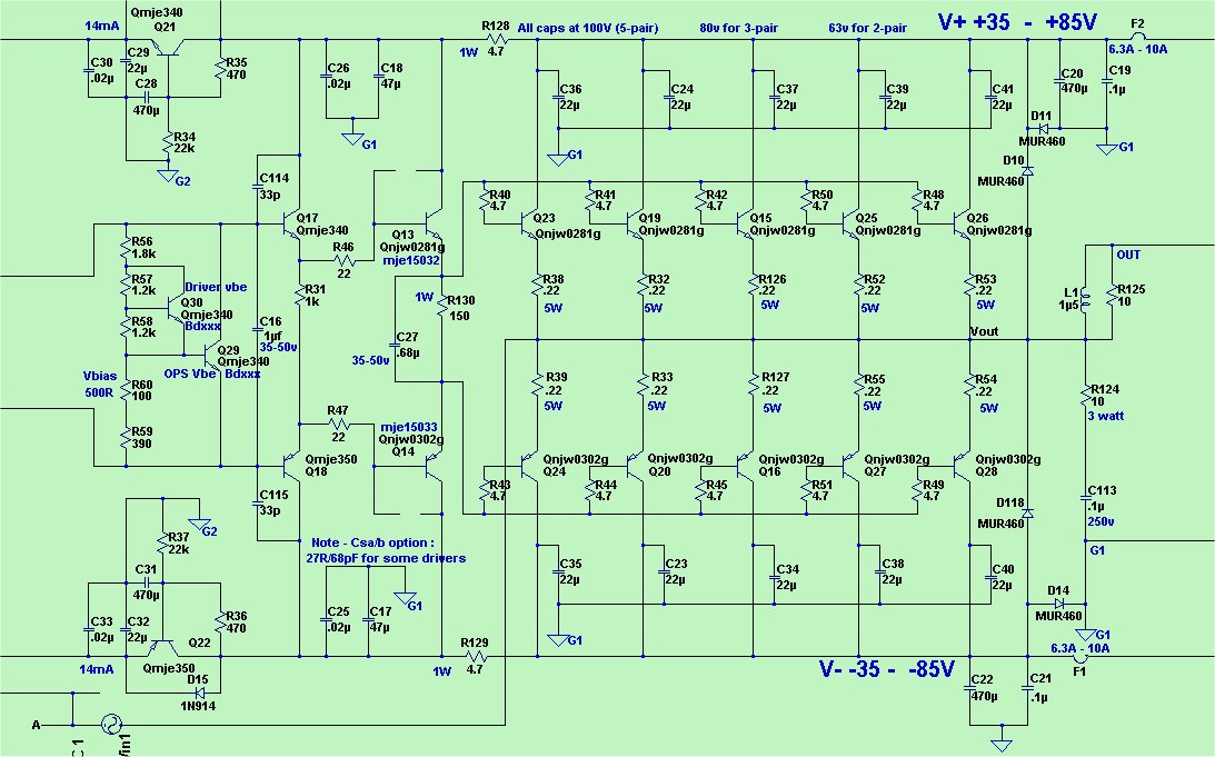
The first picture in Post # 14 IS this circuit !! 😱 Hundreds built ...
and the "redesigned one" is basically the DIYA forum's amp in the store.
OK , I'll combine the 2 (below). this amp will keep it's 70ma output bias
and 5.7ma voltage stage bias between 35-90V .... the post #1 amps will not.
Good Enough ?
He can ask me and I'll give him the EF3 output stage artwork free.
He was redesigning the ESP output stage anyways , so I thought he would like a
"safe" input stage for inspiration. If 500 builds is not "proven" , I'm a loss
of words ?
This one is also very similar to Destroyer X's "blame amp" with another 1000
builds. So all of them are "unproven" also.
BTW , what have you contributed , besides discord (I really wanted to say something really... really bad here) ?.
OS
Attachments

OS,
the OP doesn't understand the cap multiplier circuit etc etc. He needs clearly simply defined direction, like go to ... and build the Badger amp.
the OP doesn't understand the cap multiplier circuit etc etc. He needs clearly simply defined direction, like go to ... and build the Badger amp.
Your joke is much better than mine 😉
You call this a
as in: crazymechanic builds what's shown in that schematic and it will work?
Leaving aside the small details of suggested PCB, layout, suggested supply and power transformer, heatsinks, etc.
Boy, your Faith must move mountains indeed 😀
Even if you add this (although you are leaving the details for crazymechanic to solve 😉 )
Only in DIY Audio can a small snippet of an amp simulation be considered a fully working and developed project 😛
Oh ..... really? ...... a review of 2 incomplete circuit snippets?
EDIT: psssst ! I'm just whispering: it even shows wires going out of the picture and it does not show where/how they are connected, at least show a full, buildable schematic and we can talk
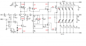
That output board is definitely a proven working design. I have 6 of them working myself along with four different input designs to plug into it. If you print both the schematics and place them against each other the lines will connect to each other. That might be a hint how to connect it.
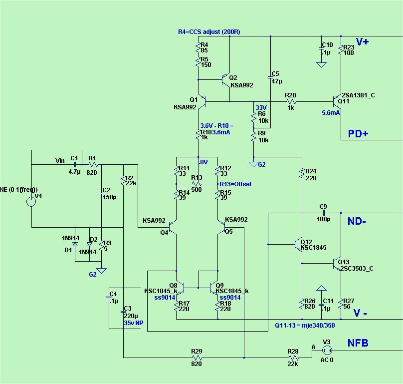
no worries guys , I have built many working amplifiers just from taking a readily working schematic. I want to do this by experimenting here.
So I put a current mirror input stage while reading about the blameless amp and thus it has a higher gain.
What'sa better VAS topology? Like the one I have in my circuit which is the one Rod used originally or a push pull version or maybe some other ? I would love to hear your thoughts.
Also aren't the + supply rail input stage current resistor values too low since we are speaking about a +70volts dc rail?
I haven't done calculations yet as I am focusing more on the schematic and design right now.
Also should I cut the middle between q10 and q11 and tie them to ground in the middle with resistors from each side in series ? Does that add stability or no , I have seen such layout in some previous amps I have made.
Attachments
Last edited:
Hi Crazy, my $0.02
- The tail current is way too high. Replace D1 with 2x series 1n4148 and increase 22R to 150R.
- You might have too much VAS degeneration, reducing OLG to low levels. I would reduce the VAS emitter resistor from 100R to 22R or remove it altogether.
- The current through your pre-drivers is probably too high to be optimal and certainly too high if you are planning to use TO92 devices with those 70V rails. A 1k Re is probably about right.
- Move the speed up cap from the pre-driver to the driver where it will be more useful. About 1uF.
- You will need to heatsink the drivers and VAS transistor.
- Approx. 0R22 to 0R33 for the output Re's.
I think this has the potential to result in a decent sounding and very powerful amplifier. I like it. My main concerns are:
- You might need to play with the bias generator I think it will be under compensated with the EF triple.
- You will need some RC decouple the main drivers' collectors to promote stablility. I would also add pads around the driver BC in case you need shunt caps to stabilise it (I have had to do this with some pre/driver/output combinations.
I'm looking forward to seeing you build this hot-Rodded Elliott design 🙂
What'sa better VAS topology?
"Better" is relative. (or even subjective).
Each has strengths and weaknesses. the "blameless" /LIN like we have been
discussing (with discord 😀) , does not clip cleanly or symmetrically.
-But it does give the most for the least.
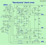
Google "leach amp" - that topology/VAS will at least do any "badness" symmetrically.
Google "hawkford cascode" , add that to the "leach" and you have my "spooky amp" - which does clip nicely.
Most 10-14 device input stages will "bottom out" at .002 - .003% distortion if
correctly designed. Much of this goodness is due to the very small load put on
the vas by using a EF3. BTW , those values at input are for the current sources-
the current will stay rock solid at @ 3.5ma regardless of supply.
Many of the symmetrical ones use a 12-33V zener regulated
input with 1-2w resistors to make any supply voltage work. (examples below).
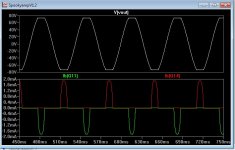
You commented on "too many parts" - BUT the ESP amp would not last
for 20 years in hard service at the club or party clipping all day. The "extra" devices
make for extended abusive service life. (look at the clip below -perfect) - the real
amp also does this. 🙂
OS
Attachments
BTW , what have you contributed , besides discord (I really wanted to say something really... really bad here) ?
I have contributed ... huh ..... realism? 😀
If you wanted to help crazymechanic ... which by the way, although being somewhat experienced clearly was not that sure of himself, you would straight pointed him to the XXXXX project, whatever you call it.
But you did not, just offered incomplete schematics.
Straight out of a simulation program, like if you had never actually built them.
crazymechanic had doubts [post#1] about 2 very different circuits which at least were complete, are searchable and have tons of build info easily available)
Just google >>Rod Elliot's project 3a<< or search DIY for >>Apex<< 😀
Am I wrong?
You sort of made fun of him in [post#3]
crazymechanic got some input but made it clear that he wanted practical info, not generic "opinion" ... which is fine with me.
[post#9]could you please make some quick corrections to the p3a project schematic or just explain a little more naming where the change needs to be made.
like what is an ef3 or base stoppers etc ?
He receives more theoretical suggestions, no doubt very good ... but not what he asked.
Until Ian Finch who is a realistic guy suggests [post#12]
Sugesstion with which I fully agree 🙂It would be much better to use a standard design for which a PCB is available and no mods are required.
In [post#14] you mention above, you do not send him to a project page, do not name it so what will he search? 🙄 and you post an incomplete schematic with undisclosed lines leaving it, no name, nothing.
And you suggest him to kludge that into one of his amps.
Is that REALISTIC? 🙄
Nothing personal, quite the contrary, I'm certain your design must be very good and reviews brilliant, but please agree that, given the way the thread is going, as shown is not of much help.
EDIT: by the way, Jay also seems to agree :
OS,
the OP doesn't understand the cap multiplier circuit etc etc. He needs clearly simply defined direction, like go to ... and build the Badger amp.
Last edited:
I have contributed ... huh ..... realism? 😀
If you wanted to help crazymechanic ... which by the way, although being somewhat experienced clearly was not that sure of himself, you would straight pointed him to the XXXXX project, whatever you call it.
But you did not, just offered incomplete schematics.
Straight out of a simulation program, like if you had never actually built them.
crazymechanic had doubts [post#1] about 2 very different circuits which at least were complete, are searchable and have tons of build info easily available)
Just google >>Rod Elliot's project 3a<< or search DIY for >>Apex<< 😀
Am I wrong?
You sort of made fun of him in [post#3]
crazymechanic got some input but made it clear that he wanted practical info, not generic "opinion" ... which is fine with me.
[post#9]
He receives more theoretical suggestions, no doubt very good ... but not what he asked.
Until Ian Finch who is a realistic guy suggests [post#12]
Sugesstion with which I fully agree 🙂
In [post#14] you mention above, you do not send him to a project page, do not name it so what will he search? 🙄 and you post an incomplete schematic with undisclosed lines leaving it, no name, nothing.
And you suggest him to kludge that into one of his amps.
Is that REALISTIC? 🙄
Nothing personal, quite the contrary, I'm certain your design must be very good and reviews brilliant, but please agree that, given the way the thread is going, as shown is not of much help.
EDIT: by the way, Jay also seems to agree :
It is real. i build OS design and I build my design from simulation. If you do not know how to use simulation and if you do not know how to design an amplifier, it does not mean everyone can not use simulation and can not design an amplifier.
Crazymechanic has made it pretty clear that he doesn't want an already built plug in the parts and go amp. He wants to experiment(look up a few posts). He's looking for design tips, not a finished product. Someone posting a couple reference schematics really shouldn't be that offensive. Someone saying not to try it for yourself is offensive on a DIY site. Just sayin...I have contributed ... huh ..... realism? 😀
If you wanted to help crazymechanic ... which by the way, although being somewhat experienced clearly was not that sure of himself, you would straight pointed him to the XXXXX project, whatever you call it.
But you did not, just offered incomplete schematics.
Straight out of a simulation program, like if you had never actually built them.
crazymechanic had doubts [post#1] about 2 very different circuits which at least were complete, are searchable and have tons of build info easily available)
Just google >>Rod Elliot's project 3a<< or search DIY for >>Apex<< 😀
Am I wrong?
You sort of made fun of him in [post#3]
crazymechanic got some input but made it clear that he wanted practical info, not generic "opinion" ... which is fine with me.
[post#9]
He receives more theoretical suggestions, no doubt very good ... but not what he asked.
Until Ian Finch who is a realistic guy suggests [post#12]
Sugesstion with which I fully agree 🙂
In [post#14] you mention above, you do not send him to a project page, do not name it so what will he search? 🙄 and you post an incomplete schematic with undisclosed lines leaving it, no name, nothing.
And you suggest him to kludge that into one of his amps.
Is that REALISTIC? 🙄
Nothing personal, quite the contrary, I'm certain your design must be very good and reviews brilliant, but please agree that, given the way the thread is going, as shown is not of much help.
EDIT: by the way, Jay also seems to agree :
Elliot just wants to sell boards and dribbles out concept , I offered to point him to the real artwork.
If he wanted concept while he actually listened to realism - I would also of offered that.
Someone had some bad tequila in the southern hemisphere to think otherwise.
If I pointed him directly to the "goods" , I would of been accused of "jacking" or
other selfish endeavors.
So , mr. Fahey - it is you who seem to be trolling (for discourse), while others
are just finding out where crazymechanics real interests are (and trying to help).
You still offer NOTHING - you point him to some projects. But most are not
5+ output pair , safe , proven designs - harder to do.
Search all the "DX" projects , many have built them - but only some are BIG.
OS
Last edited:
hey folks, don't worry be happy as Marley said once.
Yes indeed with this one I want to experiment as I said.All of us have went through this I believe.
As to what Ranchu32 said , some good advices that I changed in the design , indeed I looked at some other schematics of working power amps and found them necessary. As for the predriver current resistor , isn't 1k a bit too much? I looked at some other designs with bd139/140 and they have someting around 390 to 560 ohms, with similar supply voltages on rails.
I laughed when you said this
I am thankful for your input and suggestions , I mean the best thing you could do to help me out is correct some more , maybe something little or some details to make it a batter amp than it is now.
As Ranchu pointed out I'm too am worried about the bias current and the VAS stage.Maybe I should get rid of the lower 2x 3.3k resistors and the capacitor that ties to the output feedback and instead use a second transistor making three transistors in total for the VAS , with the bias transistor and regulator in the middle or should I leave it as it is?
Do you think the bias will not be able to generate enough current to keep the cascade of output devices with a steady bias current? Maybe I should use stringer transistors for the VAS stage with higher current rating and then I could have a higher bias current reserve?
What do you think about the input stage is it ok are the resistor nominals good enough or no?
P.S. Heres a pretty wild guess and a question at the same time. I had two ideas in my mind , first one for output cascade amplifiers like this one and others , would it be possible to use two bias generators so to speak of , one smaller for VAS and predrivers since they are the ones that prepare the signal to be fed into the output transistor bases so the signal must be as close to original as possible and then have another bias current source for the output alone, the output bias would just sense the thermal operation of just the output without worrying about the VAS and the VAS and predriver/driver bias would take care of those parts , given sufficiently large heatsinks the output generates much more heat than the VAS. I;m not saying this is a good idea just askign what you think.
The other idea is that if we have an output cascade like I have here of 5 trasistors on each side. MAybe one could make a topology where only one pair the first one has a constant bias current and is open and eliminates the distortion associated with it and then the next pairs switch on only with increasing output levels or in this case base voltage/currents.
Something similar to class H just that instead of jerking the rail voltage we could instead use kmore or less transistor pairs depending on what load we are driving and how much power we require at that point.
I guess the fail here would be that it wouldn't be possible to make the rest transistors switch on when needed in a linear enough fashion as to not mess wtih the output sine wave.Anyway some commentary is welcomed.
Yes indeed with this one I want to experiment as I said.All of us have went through this I believe.
As to what Ranchu32 said , some good advices that I changed in the design , indeed I looked at some other schematics of working power amps and found them necessary. As for the predriver current resistor , isn't 1k a bit too much? I looked at some other designs with bd139/140 and they have someting around 390 to 560 ohms, with similar supply voltages on rails.
I laughed when you said this
Hot Rodded , If this amp will work in the end I think Rod should get notified about a new design but especially about a new way to refer to amps made by Elliot but later tuned " Hot Rodded" 😀😀I'm looking forward to seeing you build this hot-Rodded Elliott design 🙂
I am thankful for your input and suggestions , I mean the best thing you could do to help me out is correct some more , maybe something little or some details to make it a batter amp than it is now.
As Ranchu pointed out I'm too am worried about the bias current and the VAS stage.Maybe I should get rid of the lower 2x 3.3k resistors and the capacitor that ties to the output feedback and instead use a second transistor making three transistors in total for the VAS , with the bias transistor and regulator in the middle or should I leave it as it is?
Do you think the bias will not be able to generate enough current to keep the cascade of output devices with a steady bias current? Maybe I should use stringer transistors for the VAS stage with higher current rating and then I could have a higher bias current reserve?
What do you think about the input stage is it ok are the resistor nominals good enough or no?
P.S. Heres a pretty wild guess and a question at the same time. I had two ideas in my mind , first one for output cascade amplifiers like this one and others , would it be possible to use two bias generators so to speak of , one smaller for VAS and predrivers since they are the ones that prepare the signal to be fed into the output transistor bases so the signal must be as close to original as possible and then have another bias current source for the output alone, the output bias would just sense the thermal operation of just the output without worrying about the VAS and the VAS and predriver/driver bias would take care of those parts , given sufficiently large heatsinks the output generates much more heat than the VAS. I;m not saying this is a good idea just askign what you think.
The other idea is that if we have an output cascade like I have here of 5 trasistors on each side. MAybe one could make a topology where only one pair the first one has a constant bias current and is open and eliminates the distortion associated with it and then the next pairs switch on only with increasing output levels or in this case base voltage/currents.
Something similar to class H just that instead of jerking the rail voltage we could instead use kmore or less transistor pairs depending on what load we are driving and how much power we require at that point.
I guess the fail here would be that it wouldn't be possible to make the rest transistors switch on when needed in a linear enough fashion as to not mess wtih the output sine wave.Anyway some commentary is welcomed.
Attachments
I'll say it simply, that tinkering and "trying things" with high power amplifiers is risky and any mistakes are expensive. Fires can erupt violently and destroy almost everything before you even notice or react.
Do you see any safety circuits on the designs posted here? 😕
Nobody has even considered them yet but anyone thinking 500W or so is gonna be a snap, should consider the necessary integration of protection circuits into those half-baked schematics. There is a clue here, in this admission by Rod Elliott, but it is only one safety aspect:
Folks here may not read Randy Slone's books much now but they don't require a science degree or electronics background to follow and get started on high power audio. Read this - it's a large book, pitched right at your interest and you'll find it useful and engaging if you don't need a translation. Hint - A lot of text and design discussion is visible in the preview:
High-Power Audio Amplifier Construction Manual: 50 to 500 Watts for the Audio Perfectionist: Amazon.co.uk: G. Randy Slone: 9780071341196: Books
Do you see any safety circuits on the designs posted here? 😕
Nobody has even considered them yet but anyone thinking 500W or so is gonna be a snap, should consider the necessary integration of protection circuits into those half-baked schematics. There is a clue here, in this admission by Rod Elliott, but it is only one safety aspect:
Get serious with serious power - use a proven design because with attention to detail, it can work as designed - not just hoping that a super-sized version of something very basic should work because in theory it could and we can only guess why not. Big amps aren't hifi toys. If it were possible to build them simple and yet safe for general purpose or arbitrary use, they would have been so but look at what is out there, pro or amateur - see anything without protection circuits?ESP P68 project notes There is NO SHORT CIRCUIT PROTECTION. The amp is designed to be used within a subwoofer or other speaker enclosure, so this has not been included. A short on the output will destroy the amplifier.
Folks here may not read Randy Slone's books much now but they don't require a science degree or electronics background to follow and get started on high power audio. Read this - it's a large book, pitched right at your interest and you'll find it useful and engaging if you don't need a translation. Hint - A lot of text and design discussion is visible in the preview:
High-Power Audio Amplifier Construction Manual: 50 to 500 Watts for the Audio Perfectionist: Amazon.co.uk: G. Randy Slone: 9780071341196: Books
I'll say it simply, that tinkering and "trying things" with high power amplifiers is risky and any mistakes are expensive. Fires can erupt violently and destroy almost everything before you even notice or react.
I use a low power 30VAC 50VA transformer for testing.
If a short occurs then the transformer cant put out more than a few amps.
If there is a problem the transformer buzzes and I can turn off the mains before the output transistors blow. There has been only once in 7 years when a output transistor went that I didn't catch it quick enough.
I use crocodile clips for power etc so it is quick connecting.
It amazes me just how loud the amplifiers can go with this small transformer.
Tinkering with my first big supply amp always brought up project 117's warning
in my head (below). He DID use current sources on this one 😀 !
Nigel's right with the small supply also , I use a 2A 150VA 40-0-40Vdc supply to test an new amp.
I even run it with just the driver stage "jury rigged" to feedback. 2-68R's (for a 150R)
2 X 100R (for a 220R Re) attached to the feedback resistor.
Bias them for <1.1V (BJT) , you can check your whole input stage , VAS , and driver stage
with out a single burnt output device.
At 1.1V , when you do solder in the outputs (I start with one pair) you will be
initially underbiased with NO risk of magic smoke.
I am going to make a dedicated test rig to do more designs on , it will have
2 -60W incandescent's or 100W quartz lamps in series with the 40-0-40 rails,
as well as a dc detect between test amp and speaker.
OSWARNING This project describes an amplifier, power supply and tests procedures that are all inherently dangerous. Nothing described in this article should even be considered unless you are fully experienced, know exactly what you are doing, and are willing to take full 100% responsibility for what you do. There are aspects of the design that may require analysis, fault-finding and/or modification.
By continuing to read this article and/or commencing work on the project, you provide your implicit agreement that ESP shall be held harmless for any loss or damage, howsoever caused. You accept all risks to life, limb and finances (this will be a very expensive undertaking) that the project may present. ESP accepts that there may be errors and/or omissions in the text and diagrams that follow, and you accept that these become your responsibility should you decide to build the project.
No assistance whatsoever will be provided for this project! If you ask me questions about it, they WILL NOT be answered!
Last edited:
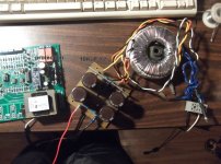
Here is my test rig.
An externally hosted image should be here but it was not working when we last tested it.
P.S. Heres a pretty wild guess and a question at the same time. I had two ideas in my mind , first one for output cascade amplifiers like this one and others , would it be possible to use two bias generators so to speak of , one smaller for VAS and predrivers since they are the ones that prepare the signal to be fed into the output transistor bases so the signal must be as close to original as possible and then have another bias current source for the output alone, the output bias would just sense the thermal operation of just the output without worrying about the VAS and the VAS and predriver/driver bias would take care of those parts , given sufficiently large heatsinks the output generates much more heat than the VAS. I;m not saying this is a good idea just askign what you think.
The other idea is that if we have an output cascade like I have here of 5 trasistors on each side. MAybe one could make a topology where only one pair the first one has a constant bias current and is open and eliminates the distortion associated with it and then the next pairs switch on only with increasing output levels or in this case base voltage/currents.
Something similar to class H just that instead of jerking the rail voltage we could instead use kmore or less transistor pairs depending on what load we are driving and how much power we require at that point.
I guess the fail here would be that it wouldn't be possible to make the rest transistors switch on when needed in a linear enough fashion as to not mess wtih the output sine wave.Anyway some commentary is welcomed.
Current mirror on this circuit must be PNP type.
Using bootstrap resistor with triple emitter follower seem useless. VAS output impedance still lower. You can use constant current source for VAS load.
You can consider to use other compensation to increase slew rate and decrease THD at 20kHz.
I do not understand of using 10 ohm resistor series with decoupling cap at output transistor.
Using a pro- amp trafo/PS to power that thing ? (Nice big amp- BTW).
Mine is quite humble , A E- waste logitech trafo with my first toner transfer
PS (4 X 4700u). (below)
The big board is a "protector" - temp./overcurrent/DC/ ...AC even. 🙂
Need to buy the lamps and mount it all on a nice Tennessee OAK board. 😀
(bottom of a moonshine barrel) ...
OS
Mine is quite humble , A E- waste logitech trafo with my first toner transfer
PS (4 X 4700u). (below)
The big board is a "protector" - temp./overcurrent/DC/ ...AC even. 🙂
Need to buy the lamps and mount it all on a nice Tennessee OAK board. 😀
(bottom of a moonshine barrel) ...
OS
Attachments
I use a low power 30VAC 50VA transformer for testing.
If a short occurs then the transformer cant put out more than a few amps.
If there is a problem the transformer buzzes and I can turn off the mains before the output transistors blow. There has been only once in 7 years when a output transistor went that I didn't catch it quick enough.
I use crocodile clips for power etc so it is quick connecting.
It amazes me just how loud the amplifiers can go with this small transformer.
This is good advice. I would also use a light bulb tester in series with the primary transformer winding and/or limiter resistors on the DC rails.
This is standard procedure for me, although I suspect the OP already has a few amplifier builds under his belt and would be aware of these precautions.
- Status
- Not open for further replies.
- Home
- Amplifiers
- Solid State
- which amp would be better...