I am looking for a new project. What is the largest Pass amp anyone here has built? Is it possible to build an X-600??
Mark
Mark
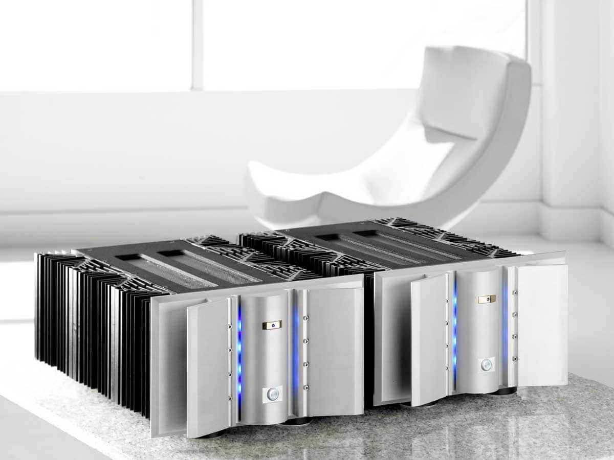
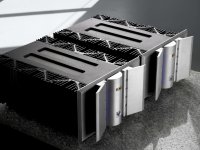
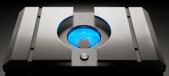
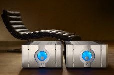
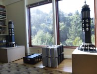
Member AR2 built a clone of the X-600 some years ago. He brought his two monoblocks to Burning Amp too IIRC.
GL
GL
Those are beautiful! I would certainly like to know more! Not like this is going to be group project or something. Just the expense of four 3KVA toroids would make most people shudder. But I would be up for it and have time to do it, also have Bridgeport vert. mill as well! I will look for his member info and write to him. Or perhaps he will see this thread...
I am not so sure DIY X Amp can be scaled up this big or not.... and still be safe.
Mark
I am not so sure DIY X Amp can be scaled up this big or not.... and still be safe.
Mark
Wow! If it wasn't for the construction pictures, it would be hard to
believe it is not a top flight commercial product.
believe it is not a top flight commercial product.
...
I am not so sure DIY X Amp can be scaled up this big or not.... and still be safe.
Mark
yes , they can
though .... I have opposite problem - even if I make smallest bridged amp possible (taking in account minimal allowable PSU voltage for output mosfets ) , that's still too much power for my needs .........

whatever ....... maybe if I use small Toshiba in output ........ with some tiny Iq .....
😛
Well, I don't need 600 watts either... I just need a big project unlike any I have done before. Then I also have excuse to buy gigantic speakers!!
Mark
Mark
If you try to build a passively cooled 50watt SOZ, it could possibly be physically the largest...
So I just sent AR2 an email... so we'll see if he is willing to share what he built with me.... I really am up for this....
Mega Amp... I was expecting you! I agree... but I would water cool it so it would still be relatively small. It might even be practical to water an cool X-600. Well, not really water but same solution of Glycol we use in D-Cinema projectors would work really well.
Mega Amp... I was expecting you! I agree... but I would water cool it so it would still be relatively small. It might even be practical to water an cool X-600. Well, not really water but same solution of Glycol we use in D-Cinema projectors would work really well.
Last edited:
naah
smaller the amp , bigger the speakers

you can always use these big donuts as chokes in properly sized big speakers
smaller the amp , bigger the speakers
you can always use these big donuts as chokes in properly sized big speakers
So I just sent AR2 an email... so we'll see if he is willing to share what he built with me.... I really am up for this....
Mega Amp... I was expecting you! I agree... but I would water cool it so it would still be relatively small. It might even be practical to water an cool X-600. Well, not really water but same solution of Glycol we use in D-Cinema projectors would work really well.
Mark,
Totally off topic, but I'm curious to know how much heat those digital projectors give off.
Looking forward to see what you end up building.
Cheers,
Dennis
Member
Joined 2009
Paid Member
Attachments
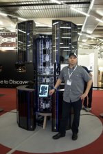
WOW! But in my case two people have to be able to move each one! How big is your line stage??!
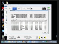
Denis Hui.... Here is a screenshot of an operating projector I just remoted into thats located in Elko, NV. This one is running a 2kw Xenon which is average size lamp. These projectors monitor a couple dozen different temps and about 20 fan speeds among other things. If a temperature or fan speed is out of normal range then the lamp is shut down and the projector throws an error code and will likely go into standby mode. There are almost 500 error codes for a given make and model. Some of the DSP chips on the T.I. boards run at 65 deg. C. If the DMD (Digital Micromirror Device) Chips run too hot it will drastically shorten their life span resulting in having to have to replace the light engine. Each DMD chip is about 3 grand for the .89" size chips and they can not be replaced in the field, only the entire prism can be swapped out... The DMD chips are liquid cooled via a pumped heat exchanger in all but the smallest DLP projectors.
Mark
Attachments
Last edited:
I recall Nelson stating that the main fig. in the supersymmetry patent was essentially the X600.
As an aside there were a number of Plitron X600 appropriate power transformers (courtesy of NP) being given away at one BA. I have two in my stash. There were still a number of them sitting on the floor begging for homes when I left that evening.
GL
As an aside there were a number of Plitron X600 appropriate power transformers (courtesy of NP) being given away at one BA. I have two in my stash. There were still a number of them sitting on the floor begging for homes when I left that evening.
GL
Hello guys,
I see my dear archivist Choky still has some of my images 🙂
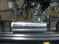
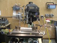
Mark, to start with, as machinist I would say, you are perfectly qualified to do it. That skill is really needed. I learned and enjoyed machining for the purpose of audio building and I still love it. With Bridgeport type knee mill, DRO and VFD control, hahaha.
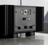
As for building the big amp I would say it is same as the small one, but with more output transistors, more heat sinks and bigger transformers. I would say it is a little bit more effort than a small one, but if you go for monoblocs, than it doesn't matter it will take time to do it.
As for the power, I needed as much as possible to feed low sensitive bass speakers in my three way system at the time. They do great job there. I never listened to them in full range, I am sure they would be great as well in that role.
My amps were built originally as X350 and later I doubled transistors from 10 to 20 per side. As for the transformers I did not go for full size but I stopped at 1500 VA So my version is not full replica of X600 but it works more than enough for what I need. Given that since I am matching them with only 30 W on the top with Choky's Bj2s. X350, X600 and X1000 are the same and are easily scalable. X350 and X600 share the same board and the difference is in amount of output pairs and transformers.
If you are thinking in doing a full monty, with original sized transformers than I would strongly advise to do it as a two chassis per one channel. The weight of one would be unbearable and very unpractical. Certainly much more involved on machining side. With amount of heat sinks I have a proper cooling and they become mildly warm.
OK let me know if you have any questions and I will answer. I will keep an eye on this thread as well. And good luck with your project.
AR2
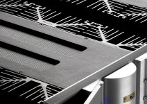
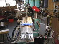
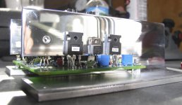
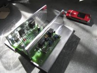
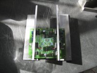
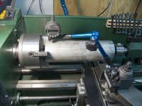
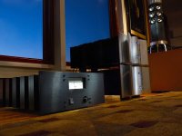
PS Here are some shots of construction process. I am sure you will appreciate these.
I see my dear archivist Choky still has some of my images 🙂
Mark, to start with, as machinist I would say, you are perfectly qualified to do it. That skill is really needed. I learned and enjoyed machining for the purpose of audio building and I still love it. With Bridgeport type knee mill, DRO and VFD control, hahaha.
As for building the big amp I would say it is same as the small one, but with more output transistors, more heat sinks and bigger transformers. I would say it is a little bit more effort than a small one, but if you go for monoblocs, than it doesn't matter it will take time to do it.
As for the power, I needed as much as possible to feed low sensitive bass speakers in my three way system at the time. They do great job there. I never listened to them in full range, I am sure they would be great as well in that role.
My amps were built originally as X350 and later I doubled transistors from 10 to 20 per side. As for the transformers I did not go for full size but I stopped at 1500 VA So my version is not full replica of X600 but it works more than enough for what I need. Given that since I am matching them with only 30 W on the top with Choky's Bj2s. X350, X600 and X1000 are the same and are easily scalable. X350 and X600 share the same board and the difference is in amount of output pairs and transformers.
If you are thinking in doing a full monty, with original sized transformers than I would strongly advise to do it as a two chassis per one channel. The weight of one would be unbearable and very unpractical. Certainly much more involved on machining side. With amount of heat sinks I have a proper cooling and they become mildly warm.
OK let me know if you have any questions and I will answer. I will keep an eye on this thread as well. And good luck with your project.
AR2
PS Here are some shots of construction process. I am sure you will appreciate these.
Attachments
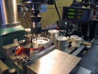
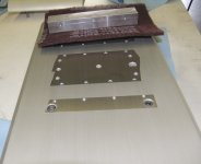
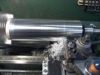
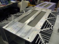
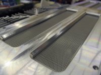
And here are some more images. As you could see I built my own heat sink for transistors that are on the board. I did also myself powder coating, what is really easy to do.
Attachments
-
 TopViewDetail.jpg227.8 KB · Views: 256
 -
 TopView.jpg314.4 KB · Views: 287
 -
 IMG_0015.jpg317 KB · Views: 276
 -
 IMG_0014.jpg315.1 KB · Views: 312
 -
 IMG_0005.jpg713.5 KB · Views: 317
 -
 IMG_0001.jpg633.6 KB · Views: 269
 -
 Amp1.jpg213.5 KB · Views: 259
 -
 _RW_0010.jpg278.5 KB · Views: 261
 -
 _RW_0003.jpg253.1 KB · Views: 321
- Status
- Not open for further replies.
- Home
- Amplifiers
- Pass Labs
- Largest Pass DIY Amp built?